iiii
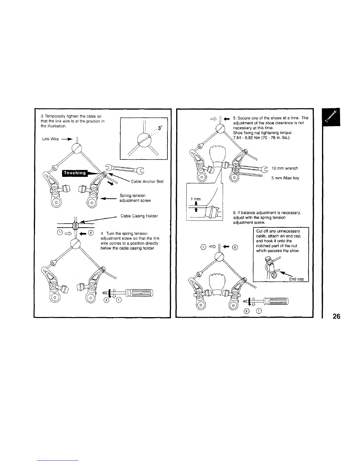
3 Temporarily tighten the cable so
that the link wire is at the position in
the illustration.
Link Wire
(DE=>
lble Anchor Bolt
Spring tension
adjustment screw
Cable Casing Holder
4. Turn the spring tension
adjustment screw so that the link
wire comes to a position directly
below the cable casing holder.
5. Secure one of the shoes at e time. The
adjustment of the shoe clearance is not
necessary at this time.
Shoe fixing nut tightening torque:
7.84 - 8.82 Nm (70 - 78 in. Ibs.)
10 mm wrench
5 mm Allen key
6. If balance adjustment is necessary,
adjust with the spring tension
adjustment screw.
Cut off any unnecessary
cable, allach an end cab,
and hook it onto the
notched part of the nut
which secures the shoe.
End cap
26