This document describes the operating instructions for the Automatic Delivery BA700, models 102-13, -13A, -13B, and -14, as of September 2004.
Function Description
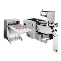
The BA700 is an automatic delivery system designed for industrial use, specifically for banding materials. It is a technically superior product that aims to achieve high levels of reliability and performance. The machine handles the transport and banding of products, likely leaflets or similar flat items, through various stations including unwinding, jogging, pressing, and ejection.
The core function involves processing a stream of products, ensuring they are correctly aligned, pressed, and banded. The machine integrates with a folding machine, and its delivery unit's height must be adjusted to the exact height of the folding machine. The system features multiple belts for transport, including flat belt drives and round belt infeeds, and a pressing station.
Key operational stages include:
- Infeed and Press: Products are fed into the machine, aligned, and pressed. The round belts are set up to guide the leaflets at a slant, and the register sheet is checked to ensure it is not ejected. The pressing station is adjusted based on product thickness.
- Layering and Shaft Infeed: The layering device's slope and length are adjustable to the product size. Guide rails ensure stability and prevent stacking up. Knurled screws are used for adjustment.
- Shaft Adjustment: The shaft's width is adjusted using a handwheel, and clamping levers secure the shaft walls. A vibration plate gear with a No. 6 socket head cap screw key is used for fine-tuning.
- Package Lift and Ejector: The machine includes a package lift table and an ejector mechanism to handle banded packages.
Important Technical Specifications
The BA700 system is controlled by an electrical control panel (BA700) which includes a CPU card, keyboard card, and output card. It features frequency converters for the press drive, band, and lifting table.
Sensors: The machine incorporates various sensors for precise operation and monitoring:
- Reflex photocell MLV40 (61.00002, 61.00014): Used for sensing ranges from 10-40mm and 25-90mm, respectively.
- Proximity switch GT3.51 (61.00001): Inductive switch for slot discs.
- Inductive switch Omron 4mm (63.00117): Inductive switch that reacts to the approach of metal, with a switching distance of 0.1-1.0mm.
- Proximity switch SME-1-S-LED-24B (61.00010): Cylinder switch for FESTO round cylinder 32dia.
- Proximity switch SMEO-4U-S-LED-24 B (61.00011): Cylinder switch for FESTO round cylinder 25dia.
- Proximity switch ZW32D-LAS (61.00004): Cylinder switch for ORIGA linear drive.
- Sensor B1 (Heat-sealers starting position): Adjustable by hand or code 204.
- Sensor B2 (Heat-sealers operating position): Adjustable by hand or code 204.
- Sensor B3 (Pressing bars working position): Adjustable by hand or code 204.
- Sensor B4 (Speed counter flat belts): Slot disc must rotate centrally in the sensor's slot. Bearing damage will destroy the sensor.
- Sensor B5 (Batch pressure): Plunger adjustment using a grub screw, distance A between plunger and pressing bar is 1-2mm.
- Sensor B7 (Speed counter infeed belts): Slot disc must rotate centrally in the sensor's slot.
- Sensors B8, B9, B11 (Counter lanes 1, 3, 2): Distance to paper approx. 20-30mm.
- Sensor B12 (Single sheet counter, Release, stream counter): Distance to paper approx. 20-30mm.
- Sensors B14, B15, B20, B21 (Elevation table positions):
- B14: Elevation table upper final position. Distance A (min 2mm, max 4mm) and C (0.5mm) between sensor B14 and elevation table.
- B20: Change-over to slow speed when travelling to upper final position. Height adjusted with B14, distance C between B20 and elevation table 0.5mm.
- B15: Elevation table lower final position. Distance B (upper edge of elevation table to upper edge of base plate) is 0-1mm.
- B21: Change-over to slow speed when travelling to lower final position. Height adjusted with B15, distance C between B21 and elevation table 0.5mm.
- Sensors B16, B17 (Pusher positions): B16 (Ground position), B17 (Final working position). Pusher must still have 2mm movement left after yellow LED lights up.
- Sensor B19 (Destacking level): Depends on product. Height adjustable through long wholes.
- Sensor B18 (Intermediate position): Depends on product, height adjustable via slots.
- Sensors B35, B36 (Side loader positions): B35 (left, final position), B36 (right, final position). Side loader must still have 2mm movement left after yellow LED lights up.
- Sensors B37, B38 (Package lift table positions): B37 (lower position), B38 (upper position). Package lift table must still have 2mm movement left after yellow LED lights up.
- Sensors B39, B40 (Pusher positions): B39 (ground position), B40 (working position). At least 75% of sensor B39/B40 must be covered by the actuator. Distance between sensor and actuator 0.5-1mm.
Pneumatics: The system uses compressed air, with a standard working pressure of 6 bar. It includes a control knob for adjusting pressure, a pressure gauge, and an oil nebulizer for refilling pneumatic oil. The pneumatic system features various valves (V1-V15) controlling functions like pressing bars, welding heads, band tension, stopper device, cooling, deflector, main valve, batch level compensator, tape tensioner, and air blow. Manual operation of valves is possible via a snap-in switch.
Belts: The manual lists various belts with their sizes and article numbers:
- Lower roundbelts: 1.580 x 4 mm (22.00017)
- Upper roundbelts: 1.610 x 4 mm (22.00052)
- Drivebelt press Unit: 1.073 x 27 mm (22.00021)
- Drivebelt stream infeed: 1.625 x 27 mm (22.00019)
- Lower belt stream infeed: 1.650 x 30 mm (22.00038)
- Upper belt stream infeed: 1.200 x 30 mm (22.00037)
- Joggingbelt: 700 x 15 mm (22.00008)
- Joggingbelt: 280 x 15 mm (22.00049)
- Small sheet lower belt: 1.260 x 30 mm (22.00010)
Usage Features
The BA700 is designed for ease of operation and precise control.
- Main Control Panel: Divided into four groups (Group I, II, III, IV) for logical organization of controls.
- Group I: Electrical buttons for switching on/off and operating the machine. Electronic keys for setting up the machine and operating it manually. Display and indicator elements for messages.
- Group II: Features a numeric keypad and function keys for batch counter, total counter, code entry, setting sheet, stream delivery, single sheet, arrow keys (up/down), Enter Key, and Delete Key.
- Group III: Includes keys for starting position, running out, manual welding, elevation table downwards, inspection, F1, F2, and side loader.
- Group IV: Displays various types of information depending on the operating mode, such as gross performance in sheets per hour, batch counter, and speed of the round belts in meters per minute. Error messages are also displayed here.
- Manual Operation: The machine can be operated manually for various functions, including setting exits, moving the elevation table, and controlling pneumatic valves.
- Programming: Frequency converters can be programmed via a keyboard (Menu, Enter, Up, Down) to adjust parameters like press drive, belt drive, and lifting table.
- Quick Check: The manual provides a quick check section to verify correct operation, including:
- Height of delivery together with the folding machine.
- Evenly diagonal transport of leaflets.
- Alignment of round belts.
- Speed difference between folding and banding machine.
- Photocells in the counter being free.
- Pressing station adjustment to product thickness.
- Flat belts transporting the stream continuously.
- Stream fed in at the mid position.
- Adjustment of guide rails in front of the shaft.
- Play in the shafts.
Maintenance Features
The manual emphasizes the importance of using "Certified palamides" Banding Materials to ensure reliability and consistency. Adjustments made to the equipment to accommodate other banding materials may void the warranty.
Safety Advice: The document includes fundamental safety advice, using "TIP," "ATTENTION!," and "Danger" warnings to highlight important information, potential hazards, and risks of injury or damage.
- Regular maintenance and care are crucial.
- Only trained personnel should operate and maintain the machine.
- Safety hoods and rotating parts must be covered.
- The machine is intended for banding folded paper; other materials may damage the machine.
- Always follow operating instructions and safety regulations.
- If necessary, supplement the operating instructions with internal safety regulations.
- Machine personnel should frequently check that all machine operators are informed and trained.
- Protective or safety devices should never be removed.
- Use only tools in perfect condition.
- Pay attention to all safety and danger tips.
- Regularly check all visible safety-related machine changes.
- Operating personnel must not wear loose clothing or jewelry.
- When running, never try to clean it.
- Ensure no other person switches the machine on while you are busy.
- Do not immediately switch the machine back on if it stops for unknown reasons.
- Always ensure the main switch and/or electrical maintenance or repair work is secured with a padlock.
- Never open the main control cabinet or lower service cabinet without authorization.
- Report any exposed cables or electrical connections.
- Safety hoods must be opened only when the machine is stopped.
- Regularly check the condition of the oil nebulizer and drain condensate out of the water separator.
Error List: The manual provides comprehensive error lists (TC166 and TC161) with conditions, descriptions, and possible causes, aiding in troubleshooting and maintenance. These lists cover issues such as:
- Photocells not covered.
- No signal transmitted from slotted disc initiator.
- Drive slip press.
- Paper jam.
- V-belt defective.
- Motor/frequency converter defective.
- Sensor defective or wrongly adjusted.
- Side loader not in normal position.
- Lifting table not in normal position.
- Package lift ejector not in normal position.
- Pressing bars need more than 2 seconds to move into the shaft.
- Welding process takes too long.
- Elevation table does not stop at intermediate position.
- Shaft protection with map device.
- Guard open.
- Emergency-Off folding machine.
- Emergency-Off button S1.
- Emergency-Off protective motor switch Q4.
- Emergency-Off contactor K6 malfunction.
- Temperature switch-off of the motors.
- Elevation table moves to delivery position and takes too long.
- Elevation table moves to starting position and takes too long.
- Time for extending/retracting welding die exceeded.
- Drives turn at too high a speed during jogging operation.
- Destacking without counter release.
- Frequency converter drive has switched off.
- Time for moving out ejectors exceeded.
- Machine goes into normal position and table does not go up.
- "Band end" has been shown on the display.
- Elevation table moves down/up.