5
Pneumatics
38
Subject to change without notice
5 Pneumatics
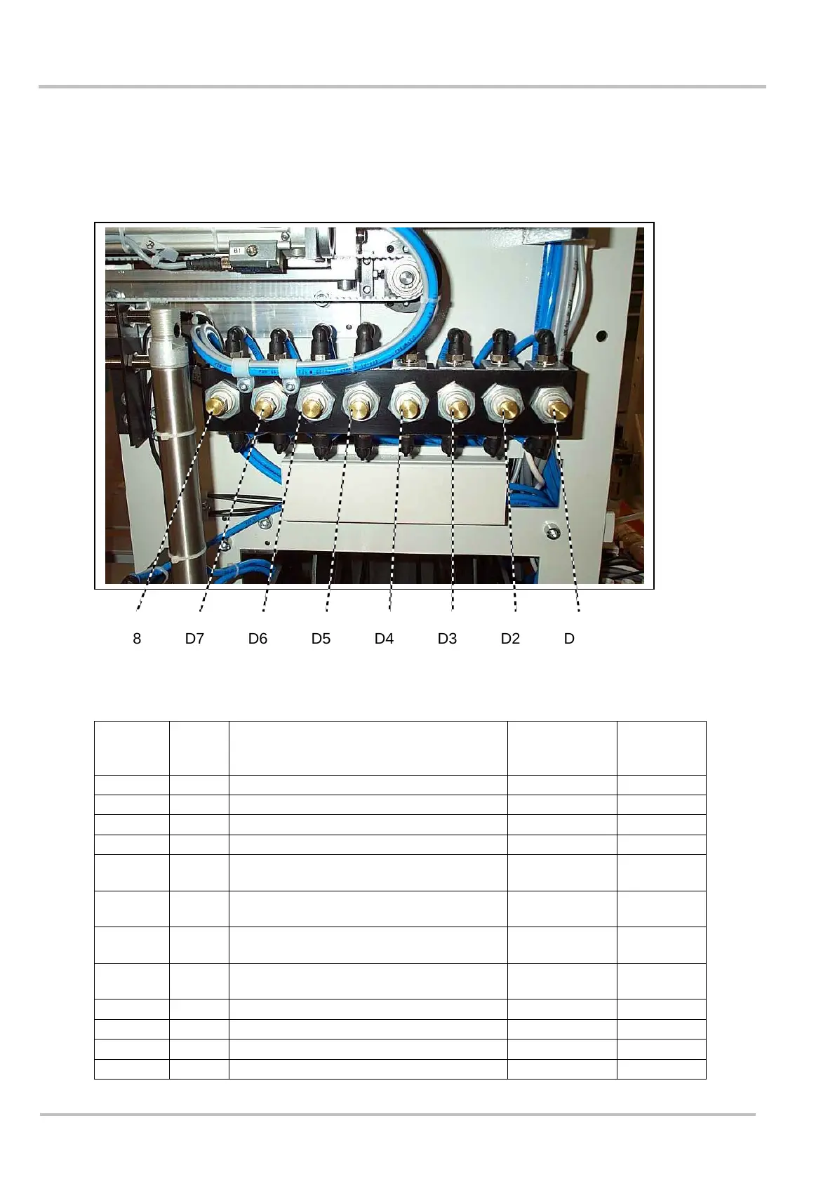
5.1 Throttle rail BA
Because of the arrangement of the throttles, the operating speed of each pneumatic valve
can be adjusted centrally.
Throttle
descrip-
tion
Valve
descr.
Function Time Output
D 1 V 5 Ejector moves to working position 800 msec Y 4
D 2 V 5 Ejector moves to starting position 400-600 msec Y 4
D 3 V 3 Lower band tensioned Y 5
D 4 V 3 Upper band tensioned Y 5
D 5 V 1 Pressing bar moves to working position 400 – 450
msec
Y 7
D 6 V 1 Pressing bar moves to starting position ( 800 msec ) Y 13 not to
measure
D 8 V 2 Welding head moves to working
position
1200 msec Y 6
D 7 V 2 Welding head moves to starting
position
1200 msec Y 6
D 13 V 13 Side loader moves to the left side 2,5 - 3 sec Y 25
D 14 V 13 Side loader moves to the right side 2,5 – 3 sec Y 25
D 15 V 14 Package lift moves to working position 3,0 sec Y 28
D 16 V 14 Package lift moves to starting position 2,0 sec Y 28
D8 D7 D6 D5 D4 D3 D2 D1