ELE-4
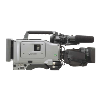
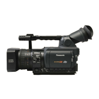
4. Connect the Extension Cable (VFK1982) to EVR connector in Unit. Then make sure that the direction of the
VFK1982 is correct as shown in Figure.
5. Supply DC6V-9V to the Measuring Board (VFK1308P). Please use the DC cable (VJA0941) and AC Adapter to
supply DC voltage to Measuring Board.
6. Connect a 9 pin RS-232C cross cable between the Measuring Board and RS-232C connector on Personal
Computer.
7. Unless otherwise specified on the message of the EVR software or this adjustment procedure, set the switches
on the Measuring Board as shown in the table below.
NAME SETTING POSITION
RS232C SEL (SW101) D-SUB
VTR TEST (SW103) NORMAL
BST TEST (SW104) NORMAL
SW107 CENTER position
SW108 H
SW105 H
SW106 OFF
FLUSH1 (SW102) NORMAL
FLUSH2 (SW109) NORMAL
When the VFK1982 is connected to EVR connector, be careful of the direction of connector on VFK1982.
Please follow as shown in the figure.
EVR CONNECTOR
 Loading...