43
Specifications
Power supply: DC 12 V
(when external power is supplied)
A
C 150 V - 240 V
(when CCU is connected)
Power consumption:
28 W (during external power
supply operation, camera only)
70
W (when CCU is connected)
indicates safety information.
Ambient temperature range:
–10 °C to +45 °C
[Preheating required at temperatures
below 0 °C]
Storage temperature range:
–
20 °C to +60 °C
Operating ambient humidity:
Less than 85 %
W
eight: Approx. 4.7 kg
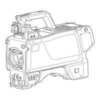
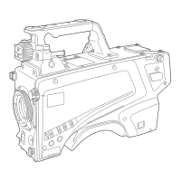
Dimensions: 135
260 360 mm
(W H
D) [excluding protrusions]
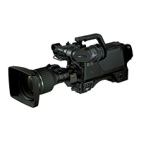
Basic items
1) Pic
kup device: 2/3˝ 2.2 million pixel IT-CCD 3
2
) System: GBR pickup system
3) Colour separation optical system:
f/1.4 pr
ism
4) Optical filters: CC: 3200K, 4300K, 6300K, Cross,
Diffusion
ND:
CAP, Through, 1/4, 1/16, 1/64
5) Lens mount: Bayonet type
6) Output standard: SMPTE 292M
7) Sensitivity: f/10.0, 2000 lux, 3200K,
white reflectance 89.9 %
(Vertical frequency: 59.94 Hz)
8) Horizontal modulation:
More than 50 % (
27.5 MHz)
9) S/N ratio: 60 dB typ. (Y: 30 MHz)
10) Horizontal frequency:
33.716 kHz, 1125-line frame
(Vertical frequency: 59.94 Hz)
2
8.125 kHz, 1125-line frame
(Vertical frequency: 50 Hz)
11) Vertical frequency:
59.94 Hz or 50 Hz, inter
lace
Input/output signals
1) MIC input:
–60 dBu to +4 dBu
(XLR
3-pin female
2)
Gain selected by camera menu
2
) INCOM: Input: –60 dBu to –10 dBu
Output: 100 mW max
(XLR, 5-pin f
emale
2)
(Mixing is controlled separately for
PGM1 and PGM
2.)
3) HD-SDI1/HD-SDI2 output:
HD signal = 0.8
V [p-p], 75 ohms (BNC)
The HD-SDI
2 signal output can be
added to the regular images using the
camera menu item setting and switched
to the VF or RET image output.
4)
Prompt output: VBS signal = 1 V [p-p], 75 ohms (BNC)
G/L input: Tri-level SYNC or black burst (BNC)
Selected using a switch.
5)
AUX BNC
• HD RET input: HD analogue signal = 1 V [p-p],
75 ohms (BNC)
• Prompt
2 output: VBS signal = 1 V [p-p], 75 ohms (BNC)
(When the CCU has a Prompt
2 input)
• Down converter output (supported as an option):
VBS or D1 signal = 1 V [p-p] or
0.8 V [p-p], 75 ohms (BNC)
Input or output can be selected using
the camera menu item setting.
6)
DC OUT: 12 V, MAX. 1 A
Control
1) P
ower selection: CCU, OFF, EXT
2) USER 1, 2, 3: Functions specified by menu items can
be allocated to the switch.
3
) RET A/B selection:
F
or selecting the return signal
4) Monitor selection:
Y/C, NAM, R, G, B
5) RET, PTT SW: RET, PTT
6) Gain selection: LOW, MID, HIGH
7) Output selection: CAM, BAR, TEST
8) White balance mode:
A, B
, preset
9) Shutter speed selection:
1/60, 1/100, 1/1
25, 1/250, 1/500,
1/1000, 1/1500, 1/2000
10) AWB, ABB settings
11) Menu selection
1
2) CALL SW
13) INCOM: MIC ON/OFF, receiving level or PGM
level
14) MIC setting: MIC po
wer, MIC gain, MIC1 selection
15) Optical filter setting:
REM, LOCAL selection and LOCAL
setting
16) Back light SW (rear panel):
ON/OFF
* When the CCU is connected, the selection functions
for 6) to 10) are not effective.
Control is exercised from the ROP or MSU.
Weight and dimensions shown are approximate.