H
L
M
N
*7
/N
*8
K
EX
PC SC
I J
G
OFF ON
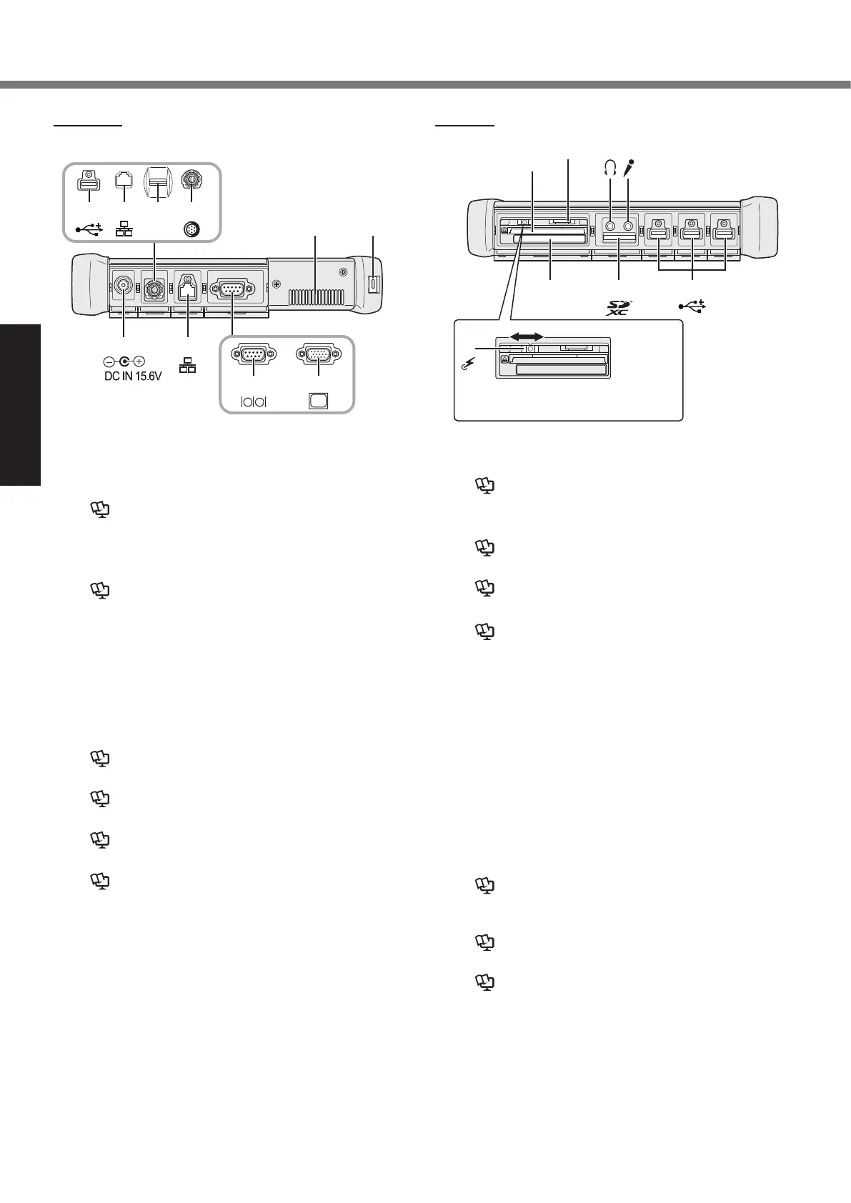
DC-IN JackA:
LAN PortB:
è
Reference Manual “LAN”
Serial PortC:
*1
/ VGA Port
*2
*1
<Only for model with serial port>
*2
<Only for model with VGA port>
è Reference Manual “External Display”
Security LockD:
A Kensington cable can be connected.
For further information, read the manual that comes
with the cable.
Ventilation Hole (Exhaust)E:
4th USB2.0 PortF:
*3
/ 2nd LAN Port
*4
/ Fingerprint
Reader
*5
/ Rugged USB2.0 Port
*6
*3
<Only for model with 4th USB2.0 port>
è Reference Manual “USB Devices”
*4
<Only for model with 2nd LAN port>
è Reference Manual “LAN”
*5
<Only for model with Fingerprint reader>
è Reference Manual “Fingerprint Reader”
*6
<Only for model with rugged USB2.0 port>
è Reference Manual “USB Devices”
Wireless SwitchG:
è
Reference Manual “Disabling / Enabling Wire-
less Communication”
ExpressCard SlotH:
è
Reference Manual “PC Card / ExpressCard”
SD Memory Card SlotI:
è
Reference Manual “SD Memory Card”
USB2.0 PortsJ:
è
Reference Manual “USB Devices”
Microphone JackK:
A condenser microphone can be used. If other types
of microphones are used, audio input may not be pos-
sible, or malfunctions may occur as a result.
Headphone JackL:
Youcanconnectheadphonesorampliedspeakers.
When they are connected, audio from the internal
speakers is not heard.
SIM Card SlotM:
<Only for model with wireless WAN>
Insert the SIM card into the SIM card slot with the
contact side facing downward and with the cut corner
oriented forward.
è
Reference Manual “Wireless WAN”
PC Card SlotN:
*7
/ Smart Card Slot
*8
*7
<Only for model with PC Card slot>
è Reference Manual “PC Card / ExpressCard”
*8
<Only for model with Smart Card slot>
è Reference Manual “Smart Card”
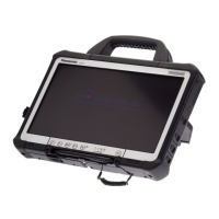
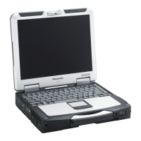
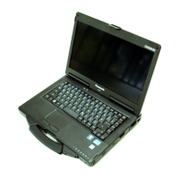
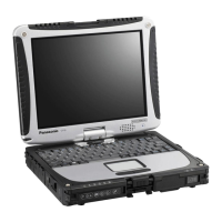
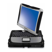
Description of Parts
Right side
Parts (F) illustrated below are all optional.
Left side
To set the wireless switch to ON,
slide and align it to the mark.
A B
FF
*
3
*
4
*
5
F
*
6
C C
E D
*
1
*
2
F

 Loading...