– 32 –
MAC9512086C2
CS-A181KR
Servicing Information
(A) Disassembly of the parts (Indoor Unit)
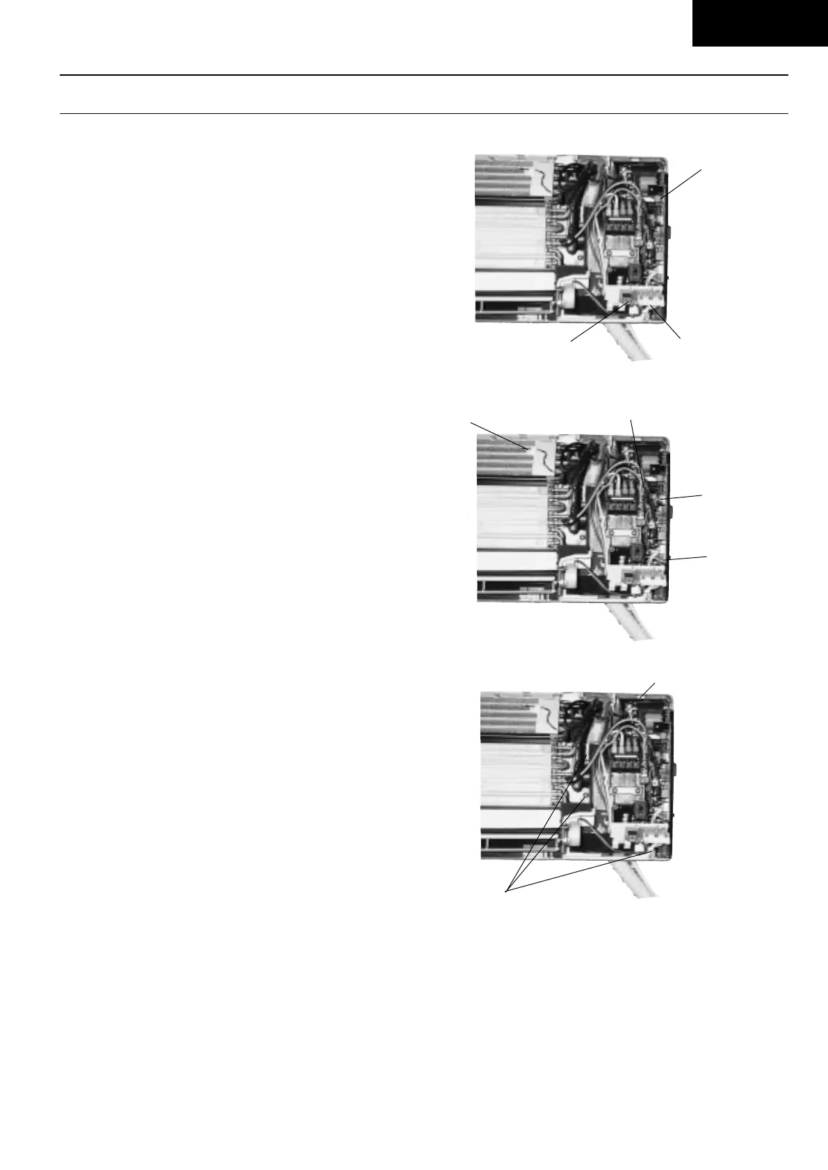
● Inspection points for the Indoor Electronic Controller
1. The Electronic Controller, a signal Receiver and an
Indicator can be seen by removing the Front Grille
and Control Board Cover, as shown in the Fig. 1.
● Indoor Fan Motor removal procedure
1. Remove the connector CN-MTR (GREEN) of Fan
Motor and connector CN-STM (GREEN) of stepping
motor from the electronic controller. Release the
earth wire (YELLOW-GREEN) from the control board
terminal and sensors from its holders. (Refer Fig. 2.)
2. Remove the Control Board.
As shown in Fig. 3, remove the 3 screws and release
the tab at the top of Control Board. Pull the Control
Board forward slightly.
Caution: Removal of Discharge Grille before removing
the control board is necessary to avoid
damaging other parts.
Fig. 1
Signal Receiver
Electronic
Controller
Fig. 2
Sensors
Earth Wire
Indicator
CN-MTR
(GRN)
CN-STM
(GRN)
Screws
Fig. 3
Taps
Untitled-3 6/10/00, 3:14 PM32