45
11.3.4 Connect the cable to the Outdoor Unit
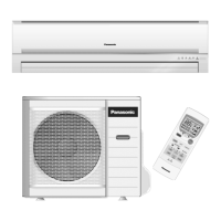
a) INDOOR POWER SUPPLY MODEL (1.0~2.5HP)
1 Remove the control board cover from the
unit by loosening the screw.
2 Connecting cable between indoor unit and
outdoor unit shall be approved
polychloroprene sheathed 5 x 1.5mm
2
(1.0~1.5HP) or 5 x 2.5mm
2
(2.0~2.5HP)
flexible cord, type designation 245 IEC 57 or
heavier cord.
3 Secure the cable onto the control board with
the holder.
4 Attach the control board cover back to the
original position with the screw.
5 For wire stripping and connection requirement,
refer to instruction g of the indoor unit.
• Earth wire shall be Yellow/Green (Y/G) in colour and longer than the other AC wires for safety reason.
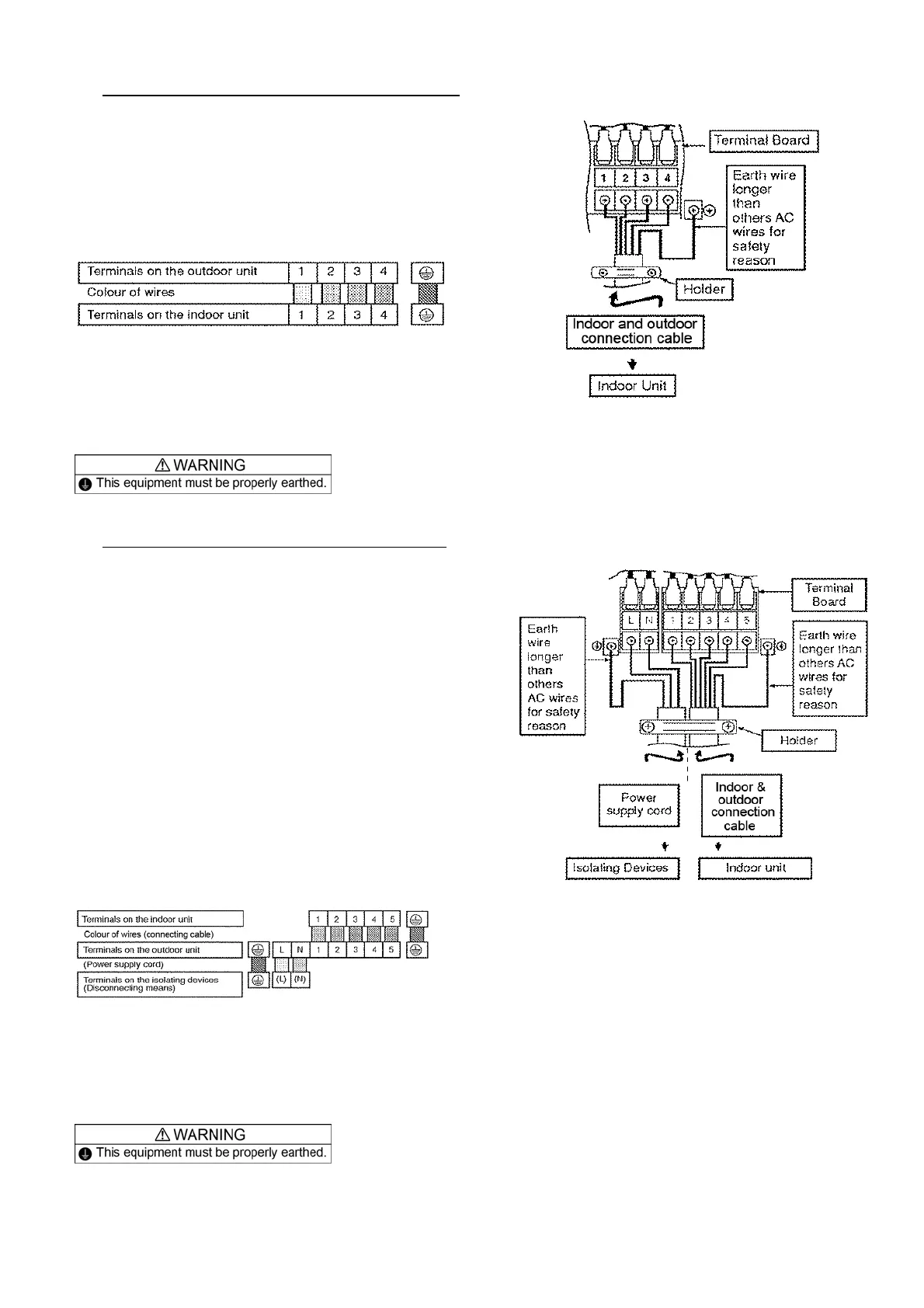
b) OUTDOOR POWER SUPPLY MODEL (3.0HP)
1 Remove the control board cover from the
unit by loosening the screw.
2 Cable connection to the power supply through
Isolating Devices (Disconnecting means).
• Connecting approved type
polychloroprene sheathed power supply
cord 3 x 4.0mm
2
(3.0HP), type
designation 245 IEC 57 or heavier cord to
the terminal board, and connect the other
end of the cord to Isolating Devices
(Disconnecting means).
3 Connection cable between indoor unit and
outdoor unit shall be approved
polychloroprene sheathed 6 x 1.5mm
2
flexible
cord, type designation 245 IEC 57 or heavier
cord.
4 Connect the power supply cord and
connecting between indoor unit and outdoor
unit according to the diagram below.
5 Secure the power supply cord and connecting
cable onto the control board with the holder.
6 Attach the control board cover back to the
original position with the screw.
7 For wire stripping and connection requirement,
refer to instruction g of the indoor unit.
• Note: Isolating Devices (Disconnecting means) should have minimum 3.0 mm contact gap.
• Earth wire shall be Yellow/Green (Y/G) in colour and longer than the other AC wires for safety reason.