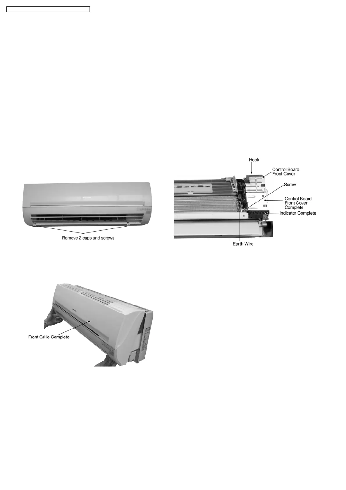
• Electronic controller and Display Complete unit can be seen
by following the below removal procedures.
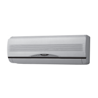
Fig. 1
− Remove the 2 caps and 2 screws at the bottom of the
Front Grille.(Fig.1)
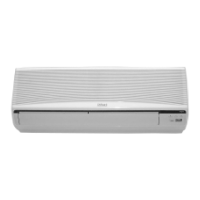
Fig. 2
− Remove the Front Grille Complete. (Fig.2)
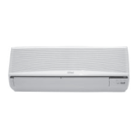
Fig. 3
− Release the hooks on top and on the left side of Control
Board Front Cover.(Fig.3)
− Then remove the Control Board Front Cover.(Fig.3)
− Remove the earth wire.(Fig.3)
− Release the screw on the left side of the Control Board
Front Cover Complete.(Fig.3)
− Then remove the Control Board Front Cover
Complete.(Fig.3)
12 Servicing Information
12.1. Distinction of Lead Free (PbF) Printed Circuit Board
• Printed circuit boards (manufactured) using lead free solder will have a PbF stamp on the Printed Circuit board.
CAUTION
• Pb free solder has a higher melting point than standard solder; typically the melting point is 50 - 70°F (30 - 40°C) higher.
Please use a high temperature solder iron and set it to 700 ± 20°F (370 ± 10°C).
• Pb free solder will tend to splash when heated too high (about 1100°F/600°C).
• If you must use Pb solder, please completely remove all of the Pb free solder on the pin or solder area before applying Pb
solder. If this is not pratical, be sure to heat the Pb free solder until it melts, before applying Pb solder.
12.2. Indoor Electronic Controller Removal Procedures
52
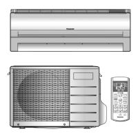
CS-C9DKU CU-C9DKU / CS-C12DKU CU-C12DKU