EasyManua.ls Logo

Panasonic CS-E9GKEW - Service Manual

Panasonic CS-E9GKEW
77 pages
To Next Page IconTo Next Page
Loading...
© 2007 Panasonic HA Air Conditioning (M) Sdn
Bhd (11969-T). All rights reserved. Unauthorized
copying and distribution is a violation of law.
Order No: MAC0704001A2
TABLE OF CONTENTS
1. Safety Precautions.........................................3
2. Specifications.................................................5
2.1 Indoor unit ....................................................5
2.2 Outdoor Unit.................................................6
3. Features ..........................................................7
4. Location of Controls and Components .......8
4.1 Indoor Unit....................................................8
4.2 Outdoor Unit .................................................9
This service information is designed for experienced repair technicians only and is not designed for use by the general public.
It does not contain warnings or cautions to advise non-technical individuals of potential dangers in attempting to service a product.
Products powered by electricity should be serviced or repaired only by experienced professional technicians. Any attempt to service
or repair the products dealt with in this service information by anyone else could result in serious injury or death.
WARNING
In order to avoid frostbite, be assured of the refrigerant leakage during the installation or repairing of refrigeration circuit.
PRECAUTION OF LOW TEMPERATURE
Please file and use this manual together with the service manual for Model No. CU-2E18CBPG, CU-
3E23CBPG, CU- 4E27CBPG, Order No. RAC0209005C2, Model No. CU-3E18EBE, Order No.
RAC0503011C2 and Model No. CS-E9GFEW, CS-E12GFEW, CS-E18GFEW, Order No. RAC0704001C2.
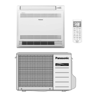
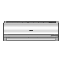
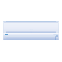
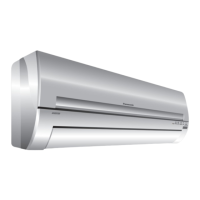
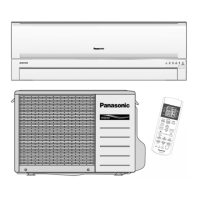
INDOOR UNIT
CS-E7GKEW CS-E7GKDW
CS-E9GKEW CS-E9GKDW
CS-E12GKEW CS-E12GKDW
CS-E15GKEW CS-E15GKDW
CS-E18GKEW CS-E18GKDW
OUTDOOR UNIT
CU-2E15GBE
S
i
m
p
l
i
fi
e
d
Panasoni c
Panasoni c
A
U
T
O
H
E
A
T
C
O
O
L
D
R
Y
F
A
N
S
P
E
E
D
A
I
R
S
W
I
N
G
e
-
I
o
n
P
A
T
R
O
L
O
F
F
/
O
N
T
E
M
P
M
O
D
E
F
A
N
S
P
E
E
D
A
I
R
S
W
I
N
G
Q
U
I
E
T
T
I
M
E
R
P
O
W
E
R
F
U
L
O
N
S
E
T
O
F
F
C
A
N
C
E
L
1
2
3
A
C
S
E
T
C
H
E
C
K
C
L
O
C
K
R
E
S
E
T
R
C
P
a
n
a
s
o
n
i
c
I
N
V
E
R
T
E
R
A
U
T
O
H
E
A
T
C
O
O
L
D
R
Y
F
A
N
S
P
E
E
D
A
I
R
S
W
I
N
G
e
-
I
o
n
P
A
T
R
O
L
O
F
F
/
O
N
T
E
M
P
M
O
D
E
F
A
N
S
P
E
E
D
A
I
R
S
W
I
N
G
Q
U
I
E
T
T
I
M
E
R
P
O
W
E
R
F
U
L
O
N
S
E
T
O
F
F
C
A
N
C
E
L
1
2
3
A
C
S
E
T
C
H
E
C
K
C
L
O
C
K
R
E
S
E
T
R
C
P
a
n
a
s
o
n
i
c
I
N
V
E
R
T
E
R

Other manuals for Panasonic CS-E9GKEW

Questions and Answers:

Panasonic CS-E9GKEW Specifications

General IconGeneral
TypeSplit System
Heating Capacity3.2 kW
Power Supply220-240 V, 50 Hz
Coefficient of Performance (COP)3.80
Noise Level (Outdoor)47 dB(A)
RefrigerantR410A
Indoor Unit Dimensions (W x H x D)870 x 290 x 204 mm
Indoor Unit Weight9 kg
Outdoor Unit Weight30 kg
Cooling Capacity2.5 kW
Noise Level (Indoor)38 dB(A)

Summary

Safety Precautions

Specifications

Indoor Unit Specifications

Detailed technical specifications for the indoor unit models.

Outdoor Unit Specifications

Detailed technical specifications for the outdoor unit models.

Product Features

Controls and Components Location

Indoor Unit Controls and Components

Identifies controls and components on the indoor unit.

Outdoor Unit Controls and Components

Identifies controls and components on the outdoor unit.

Remote Control Layout and Functions

Details the buttons and display of the remote control unit.

Unit Dimensions

Indoor Unit and Remote Control Dimensions

Provides physical dimensions for the indoor unit and remote control.

Outdoor Unit Dimensions

Provides physical dimensions for the outdoor unit.

Refrigeration Cycle Diagram

System Block Diagram

Wiring Connection Diagrams

Indoor Unit Wiring

Details the wiring connections for the indoor unit.

Outdoor Unit Wiring

Details the wiring connections for the outdoor unit.

Electronic Circuit Diagrams

Indoor Unit Circuit Diagram

Illustrates the electronic circuit layout for the indoor unit.

Outdoor Unit Circuit Diagram

Illustrates the electronic circuit layout for the outdoor unit.

Printed Circuit Boards (PCBs)

Indoor Unit PCBs

Diagrams of the main, power, and indicator PCBs for indoor units.

Outdoor Unit PCBs

Diagrams of the outdoor unit's printed circuit board.

Installation Information

Installation Check Points

Key points to check before and during installation.

3-Way Valve Caps Shape Change

Details changes in the shape and tightening method of 3-way valve caps.

Piping Length Specifications

Details maximum allowable piping lengths and additional refrigerant requirements.

Installation Instructions

Selecting the Best Installation Location

Guidelines for choosing optimal indoor and outdoor unit placement.

Indoor Unit Installation Steps

Detailed steps for installing the indoor unit, including plate mounting and piping.

Outdoor Unit Installation and Piping

Guidance on installing the outdoor unit and connecting piping.

Operation Control Modes

Simultaneous Operation Control Logic

Rules for operating multiple indoor units concurrently.

Basic Operating Functions

Explanation of inverter control, temperature settings, and thermostat control.

Servicing Modes

Auto OFF;ON Button Functions

How to use the Auto OFF/ON button for auto operation, test run, and mode selection.

Remote Control Transmission Code Selection

Procedure to select and store remote control transmission codes.

Remote Control Button Operations

Details functions of SET, CLOCK, RESET, TIMER buttons on the remote.

Troubleshooting Guide

Refrigeration Cycle System Troubleshooting

Diagnosing issues related to pressure, temperature, and electric current.

Breakdown Self-Diagnosis Function

How to access and interpret error codes displayed by the unit.

Disassembly and Assembly Instructions

Indoor Unit Disassembly

Step-by-step guide to disassemble indoor unit components.

Outdoor Unit Disassembly

Step-by-step guide to disassemble outdoor unit components.

Technical Data

Operation Characteristics Charts

Graphs showing unit performance under various conditions.

Exploded Views and Parts List

Indoor Unit Exploded View and Parts

Visual breakdown of indoor unit parts with a corresponding list.

Outdoor Unit Exploded View and Parts

Visual breakdown of outdoor unit parts with a corresponding list.

Related product manuals