61
12. Installation Instruction
12.1 Select the Best Location
12.1.1 Indoor Unit
Do not install the unit in excessive oil fume area
such as kitchen, workshop and etc.
There should not be any heat source or steam
near the unit.
There should not be any obstacles blocking the air
circulation.
A place where air circulation in the room is good.
A place where drainage can be easily done.
A place where noise prevention is taken into
consideration.
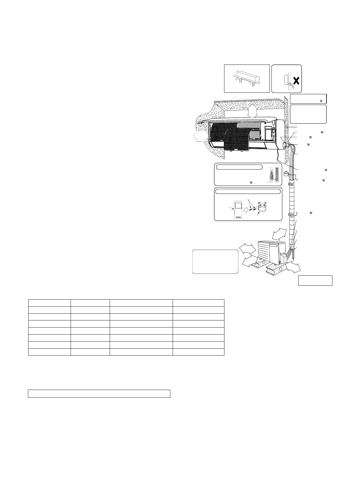
Do not install the unit near the door way.
Ensure the spaces indicated by arrows from the
wall, ceiling, fence or other obstacles.
Indoor unit of this air conditioner shall be installed
in a height of at least 1.8 m.
12.1.2 Indoor/Outdoor Unit Installation
Diagram
Table A
Model Capacity W (HP) Max. Refrigerant Charge (kg) Indoor A
min
(m
2
)
TZ20***, RZ20*** 3/4HP 0.62 Not applicable (*)
TZ25***, RZ25*** 1.0HP 0.75 Not applicable (*)
TZ35***, RZ35*** 1.5HP 0.85 Not applicable (*)
TZ42*** 1.75HP 0.87 Not applicable (*)
TZ50***, RZ50*** 2.0HP 1.33 Not applicable (*)
TZ60*** 2.25HP 1.52 Not applicable (*)
TZ71*** 2.5HP 1.82 Not applicable (*)
(*) Systems with total refrigerant charge, m
c
, lower than 1.84kg are not subjected to any room area requirements.
* Table “A” only applicable for single split connection.
* In case of connection to outdoor multi inverter, refer to installation manual at outdoor unit.
A
min
= (m
c
/ (2.5 × (LFL)
(5/4)
× h
0
))
2
** not less than safety factor margin
A
min
= Required minimum room area, in m
2
m
= Refrigerant charge in appliance, in kg
LFL
= Lower flammability limit (0.307 kg/m
)
h
0
= Installation height of the appliance (1.8 m for wall mounted)
SF
= Safety factor with a value of 0.75
** The required minimum room area, A
min
, shall also be governed by the safety factor margin formula below :
Piping direction Attention not to bend
up drain hose
(Front side)
Right
Right
Rear
Right
bottom
Left
Rear
Left bottom
Left
6
5
m
m
o
r
m
o
r
e
(Left and right are identical)
Installation plate 1
Sleeve (
)
Bushing-Sleeve (
)
Bend the pipe as closely
on the wall as possible,
but be careful that it
doesn’t break.
Saddle (
)
Putty (
)
(Gum Type Sealer)
Installation parts you
should purchase (
)
50 mm
or more
Vinyl tape (wide) (
)
• Apply after carrying
out a drainage test.
• To carry out the
drainage test,
remove the air filters
and pour water into
the heat exchanger.
•
Carry out insulation after
checking for gas leaks and
secure with vinyl tape.
Vinyl tape
Remote control holder 5
Remote control holder fixing screws 6
Remote
control 3
Insulation of piping connections
Attaching the remote control holder to the wall
Power supply cord ( )
It is advisable to avoid more
than 2 blockage directions.
For better ventilation &
multiple-outdoor installation,
please consult authorized
dealer/specialist.
5
0
m
m
o
r
m
o
r
e
(
*
)
It is advisable to avoid more
than 2 blockage directions.
For better ventilation &
multiple-outdoor installation,
please consult authorized
dealer/specialist.
Installation parts you
should purchase (
)
Connection cable ()
1/4" Liquid side piping (
)
Gas side piping (
)
Additional drain
hose (
)
1
0
0
m
m
o
r
m
o
r
e
3
0
0
m
m
o
r
m
o
r
e
1
0
0
0
m
m
o
r
m
o
r
e
1
0
0
m
m
o
r
m
o
r
e
•
This illustration is for
explanation purposes only.
 Loading...