T-11OMA/11OMCA
I f
J
CONTENTS
SAFETY
PRECAUTIONS
............................................................................................................................
2
DISASSEMBLY
INSTRUCTIONS
...............................................................................
4
GENERAL
CONNECTION
&
APPLICATIONS
.........................................................
5
FIELD
ALIGNMENT
...........................................
7
GENERAL
ALIGNMENT
............................................................................................................................
9
CIRCUIT
EXPLANATION
.........................................................................................................................
9
CONDUCTOR
VIEWS
.................................................................................................................................
9
SCHEMATIC
DIAGRAM
..........................................................................................................................
11
EXPLODED
VIEWS
..................................................................................................................................
12
REPLACEMENT
PARTS
LIST
...............................................................................................................
13
THIS
MODEL
COMPLIES
WITH
DHHS
RULES
21
CF
R
SUBCHAPTER
J
APPLICABLE
AT
DATE
OF
MANUFACTURE.
IMPORTANT
SAFETY
NOTICE
There
are
special
components
used
in
Panasonic
Video
Monitor
set
which
are
important
for
safety
These
parts
are
shaded
on
the
schematic
diagram
and
on
the
replacement
parts
list.
It
is
essential
that
these
critical
parts
should
be
replaced
with
manufacturer's
specified
parts
to
prevent
X-RADIATION,
shock,
fire,
or
other
hazards.
Do
not
modify
the
original
design
without
permission
of
Matsushita
Electric.
ABBREVIATIONS
USED
IN
THIS
MANUAL
ABL
Automatic
Beam
Limiter
AVR
Automatic
Voltage
Regulator
APC
Automatic
Phase
Control
*
CRT
Cathode
Ray
Tube
DY
Deflection
Yoke
FBT
Flyback
Transformer
OTL
Transformerless
Output
HAFC
Horizontal
Automatic
Frequency
Control
SEPP
Single
Ended
Push-Pull
Circuit
scs
Silicon-Controlled
Switch
ACC
Automatic
Color
Control
vco
Voltage-Controlled
Oscillator
SAFETY
PRECAUTIONS
GENERAL
GUIDELINES
1.
It
is
advisable
to
insert
an
isolation
transformer
in
the
power
line
and
AC
supply
before
servicing
a
hot
chassis.
2.
When
servicing,
observe
the
original
lead
dress;
especially
the
lead
dress
in
the
high
voltage
circuits.
If
a
short
circuit
is
found,
replace
all
parts
which
have
been
overheated
or
damaged
by
the
short
circuit.
3.
After
servicing,
see
to
it
that
all
the
protective
devices
such
as
insulation
barriers,
insulation
papers,
shields,
and
isolation
R-C
combinations,
are
properly
installed.
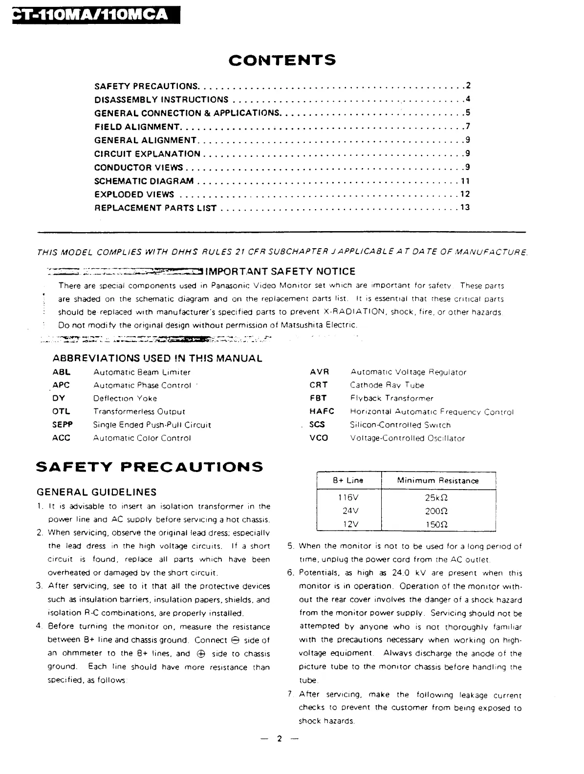
4.
Before
turning
the
monitor
on,
measure
the
resistance
between
B+
line
and
chassis
ground.
Connect
©
side
of
an
ohmmeter
to
the
B+
lines,
and
©
side
to
chassis
ground.
Each
line
should
have
more
resistance
than
specified,
as
follows:
B+
Line
Minimum
Resistance
1
16V
25kft
24V
200ft
12V
150ft
5.
When
the
monitor
is
not
to
be
used
for
a
long
period
of
time,
unplug
the
power
cord
from
the
AC
outlet.
6.
Potentials,
as
high
as
24.0
kV
are
present
when
this
monitor
is
in
operation.
Operation
of
the
monitor
with
out
the
rear
cover
involves
the
danger
of
a
shock
hazard
from
the
monitor
power
supply.
Servicing
should
not
be
attempted
by
anyone
who
is
not
thoroughly
familiar
with
the
precautions
necessary
when
working
on
high-
voltage
equipment.
Always
discharge
the
anode
of
the
picture
tube
to
the
monitor
chassis
before
handling
the
tube.
7
After
servicing,
make
the
following
leakage
current
checks
to
prevent
the
customer
from
being
exposed
to
shock
hazards.
—
2
—
 Loading...