108
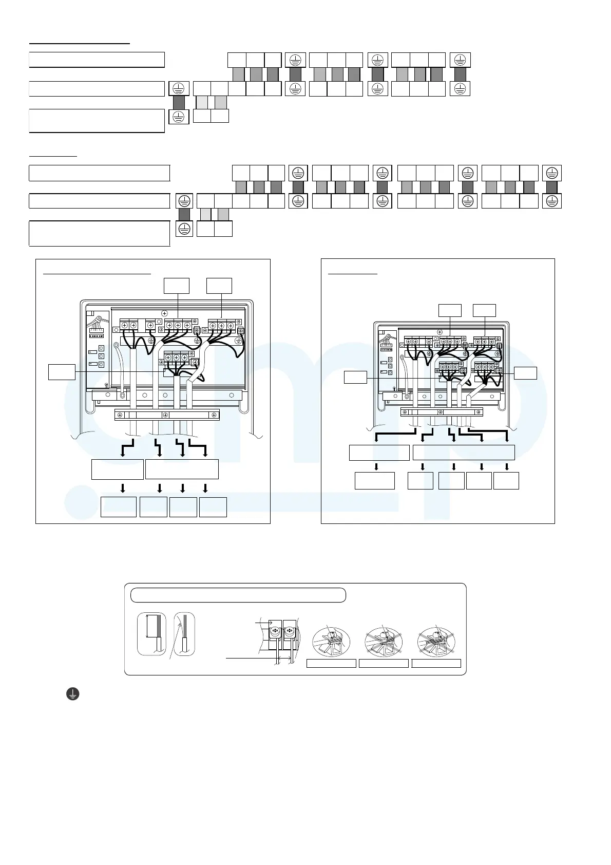
CU-3Z52***, CU-3Z68***
Colour of wires (Connection ca ble)
(Power supply cord)
Terminals on the indoor unit
Terminal s on the o utdoor unit
Terminals on the isolating d evices
(Disconnecting means)
(UNIT A ) (UNIT B)
11
11
L
(L)
22
22
N
(N)
33
33
(UNIT C)
1
1
2
2
3
3
CU-4Z68***
321tinuroodniehtnoslanimreT 123 123 123
Colour of wires (Connecting cable)
Terminals on the outdoor unit LN1 23 123 123 123
(Power supply cord)
(UNIT A) (UNIT B) (UNIT C) (UNIT D)
Terminals on the isolating devices
(Disconnecting means)
(L) (N)
p
CU-3Z52***, CU-3Z68***
Indoor & outdoor
connection cable
Unit A Unit B
Unit C
Power Supply
Cord
Isolating
Devices
Indoor
Unit A
Indoor
Unit C
Indoor
Unit B
P
Unit C
Unit A Unit B
Indoor & outdoor connection cable
Power Supply Cord
Isolating
Devices
Indoor
Unit A
Indoor
Unit C
Indoor
Unit B
Indoor
Unit D
Unit D
CU-4Z68***
5. For wire stripping and connection requirement, refer to the diagram below.
6. Secure the power supply cord and connecting cables onto the control board with the holder.
7. Attach the control board cover back to the original position with screw.
Wire stripping
(gap between
wires)
No loose strand when
inserted
Indoor/outdoor
connecting
terminal board
10 ± 1 mm
Conductor fully
inserted
Conductor over
inserted
Conductor not
fully inserted
ACCEPT PROHIBITED PROHIBITED
WIRE STRIPPING AND CONNECTING REQUIREMENT
5mm
or more
This equipment must be properly earthed.
Note: Isolating Devices (Disconnecting means) should have minimum 3.0 mm contact gap.
Earth wire shall be Yellow/Green (Y/G) in colour and longer than other AC wires for safety reason.
www.ampair.co.uk | sales@ampair.co.uk