30
11.4. Outdoor Unit
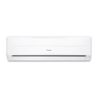
11.4.1. Install The Outdoor Unit
• After selecting the best location, start installation according to Indoor/Outdoor Unit Installation Diagram.
1. If installing the unit to a concrete base or other solid base,
use M10 or W3/8 bolts and nuts to secure the unit, and
ensure that the unit is fully upright and level.
(The anchor bolt positions are shown in the diagram at
the right side.)
In particular, install the unit at a distance from the
neighbouring building which conforms to regulations
specified by local noise emission regulation standards.
2. Do not install the outdoor unit to the building’s roof.
3. If there is a possibility that vibration may be transmitted to
the rooms of the building, place rubber insulation
between the unit and the installation surface.
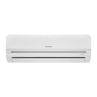
11.4.2. Connecting The Piping
11.4.2.1. Connecting The Piping To Indoor Unit
Please make flare after inserting flare nut (locate at joint portion of tube assembly) onto the copper pipe (in case of using long
piping).
Connect the piping
• Connect tube ass’y as shown in the picture. (PC36 only)
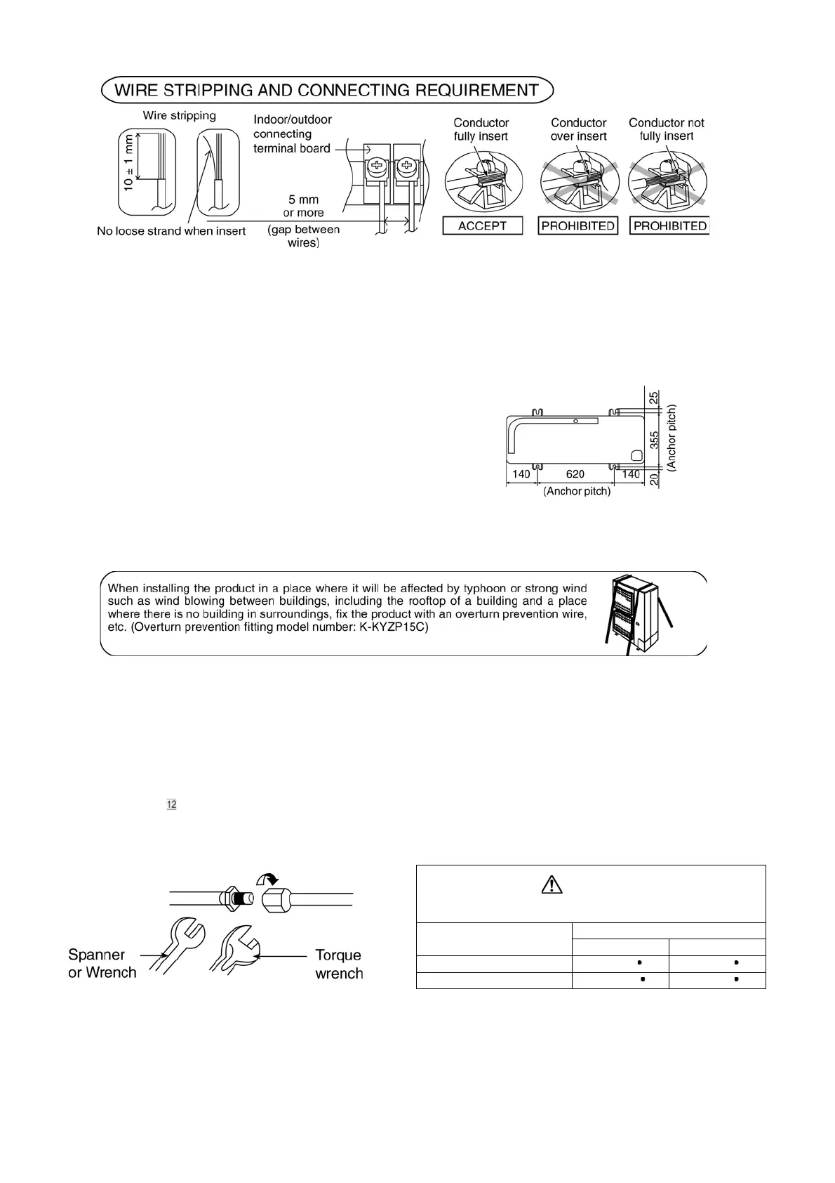
• Align the center of piping and sufficiently tighten the flare nut with fingers.
• Further tighten the flare nut with torque wrench in specified torque as stated in the table.
CAUTION
Do not over tighten, over tightening cause gas leakage.
Model
Piping size (Torque)
Gas Liquid
PC30
5/8” [65 N m] 3/8” [42 N m]
PC36
3/4” [100 N m] 3/8” [42 N m]