16
The status condition when a sensing object is present
that can be used as a baseline for the upper limit.
Upper and lower limits have
not been correctly set.
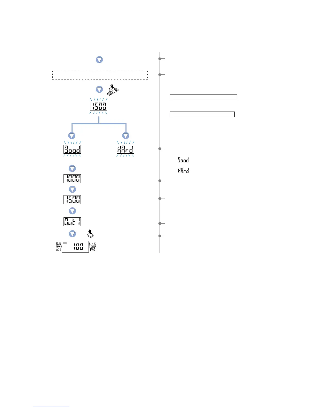
8The setting for ‘lower limit value 1_SL’ will be displayed.
9The setting for ‘upper limit value 2_SL’ will be displayed.
0The output 1 will again be displayed, indicating that
configuration is now complete.
APress the [MODE key] 5 times or keep it pressed for 2 sec.
or more, the amplifier will return to ‘RUN mode’ (normal
sensing operation).
Press the MODE key 5 times
or keep it pressed for 2 sec.
or more.
6If the [Jog switch] is pressed while in the status condition
when a sensing object is present that can be used as a
baseline for the upper limit, then the display will blink and
indicate the incident light intensity.
When utilizing thru-beam type fiber
• Press the [Jog switch] for the sensing object that has the
least amount of interrupted light.
When utilizing reflective type fiber
• Press the [Jog switch] for the sensing object with the
greatest incident light intensity .
5The unit will enter the ‘P-2’ setting state and ‘TEACH’ (yellow)
will blink on the MODE display.
7The display will indicate whether the upper and lower limits
have been correctly set or not.
• If ‘ ’ is blinking… the upper and lower limits have
been set correctly.
• If ‘ ’ is blinking… the upper and lower limits have not
been set correctly.
Incident light
intensity of P-2.
Lower limit value 1_SL
Upper limit value 2_SL
Press the
Jog switch.
Stable sensing
 Loading...