10. Disassembly and Assembly Instructions
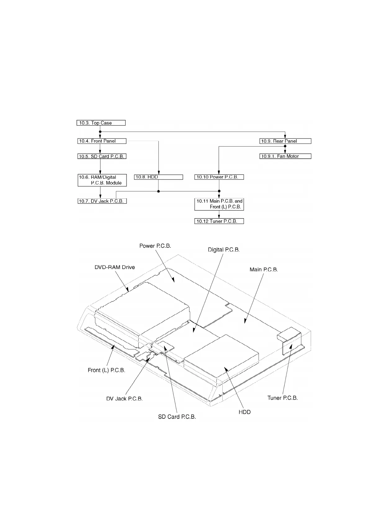
10.1. Disassembly Flow Chart
The following chart is the procedure for disassembling the casing and inside parts for internal
inspection when carrying out the servicing.
To assemble the unit, reverse the steps shown in the chart below.
10.2. P.C.B. Positions
10.3. Top Case
1. Remove 2 screws (A) and 3 screws (B).
2. Slide Top Case rearward and open the both ends at rear side of
32
 Loading...