9 MASSAGER UP/DOWN SENSOR GEAR ADJUSTMENT
METHOD
When the massager is removed from the chair, the position of the up/down sensor gear changes, resulting in a change of the
up/down stop position.
When installing the massager on the back frame, be sure to adjust the position with the up/down detection gear.
●
●●
● Up/down sensor gear position adjustment procedure
To make an adjustment, refer to the massager removing method (the back frame is tilted from the chair).
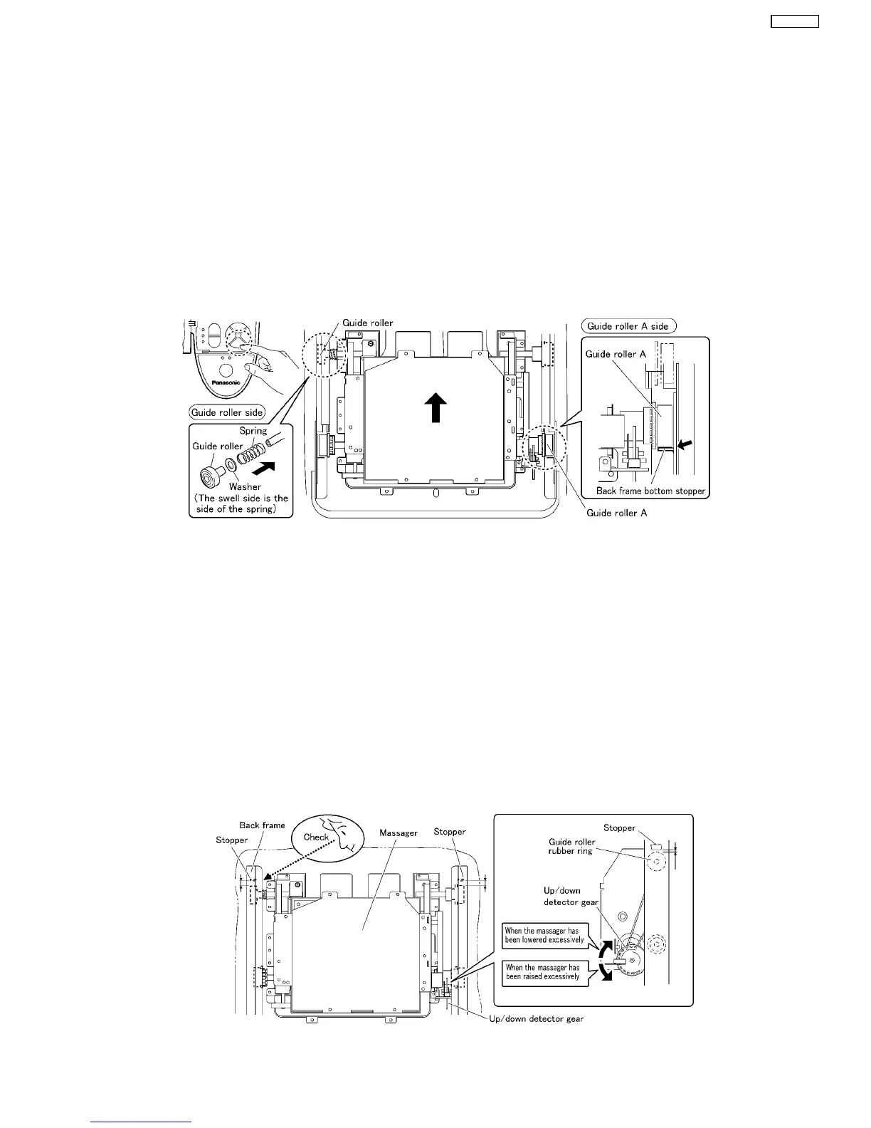
1. Before mounting, the massager on the back frame must be moved down to the lowest position by setting the controller manual
operation MASSAGE HEAD ADJUSTMENT button to DOWN.
2. Install a washer and a spring to the guide roller G in the left side and mount the massager on the lowest position of the back
frame.
3. Turn the hex nut M6 counterclockwise and move the massager upward.
4. Make sure that the massager has been mounted horizontally by moving the massager to the position shown in the Figure.
*Unless the massager has been mounted horizontally, an abnormal sound or problem may occur.
5. Move it up to the highest position (until the massager stops) by setting the controller manual operation MASSAGE HEAD
ADJUSTMENT button to up.
6. Peeping into the square hole of the back frame, check the position of the massager to adjust.
*One thread of the up/down detection gear gives a stroke change of 4mm.
When the massager has been raised excessively : Turn the up/down sensor gear counterclockwise to adjust.
When the massager has been lowered excessively : Turn the up/down sensor gear clockwise to adjust.
While adjusting the distance between the square hole and Guide roller assy. to 10mm, check by using the up/down adjustment
button found on the manual operation panel of the controller.
7. Install the rail piece A and B, and tighten uniformly the set screws (left and right, 3 pcs. each).
8. Using the manual operation of the controller, conduct the rolling operation. Set the massage heads adjustment switch to level
1, and check the up/down stroke.
13
EP1260-W7

 Loading...