13
4.
I/O Circuit Diagram
EX-11□, EX-13□, EX-19□, EX-14□
EX-11□-PN, EX-13□-PN, EX-19□-PN, EX-14□-PN
EX-15□, EX-17□
Load
100mA max.
+
−
12 to 24V DC
±10%
Sensor circuit
(Brown) +V
(Black) Output
(Blue) 0V
Load
Users’ circuitInternal circuit
50mA max.
+
−
12 to 24V DC
±10%
Color code
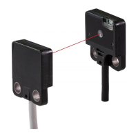
Note: The thru-beam type sensor emitter does not incorporate the output..
Load
50mA max.
+
−
12 to 24V DC
±10%
(Brown) +V
Color code
Sensor circuit
(Black) Output
(Blue) 0V
Users’ circuitInternal circuit
Note: The thru-beam type sensor emitter does not incorporate the output..
(Brown) +V
Color code
Sensor circuit
(Black) Output
(Blue) 0V
Users’ circuitInternal circuit
info@digiparts.ch
www.digiparts.ch
Ihr Schweizer Industriepartner
 Loading...