7
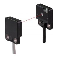
3-2 Mounting interval
● This product does not incorporate auto interference function.
In case mounting two sets
or more of the this product close together, please mount them as drawing below indi-
cates (typical example)
● Find out the operating point ℓ on the parallel deviation diagram for the setting distance L.
Separate sensors by 2 × ℓ or more.
<Installation interval for EX-11□
,
EX-15□>
In case using at sensing distance (L1) 150mm, the op-
eration point (ℓ1) is approx. 23.4mm according to dia-
gram above.
The installation interval is
Approx. 23.4mm × 2 = approx. 46.8mm
Thus, install approx.46.8mm or more away.
<Installation interval for EX-11E□
,
EX-15E□>
In case using at sensing distance (L2) 150mm, the
operation point (ℓ2) is approx. 15mm according to dia-
gram above.
The installation interval is
Approx. 15mm × 2 = approx. 30mm
Thus, install approx. 30mm or more away.
Thru-beam type: EX-11E□, EX-15E□, parallel deviation diagram (typical)
(ℓ2)
200
0
150
100
50
(L2)
Thru-beam type: EX-11□, EX-15□, parallel deviation diagram (typical)
100
(ℓ1)
50 0 50 100
200
0
150
100
50
(L1)
100 50 0 50 100
Sensing distance L (mm)
CenterLeft
Right
Operating point ℓ (mm)
100 50 0 50 100
Sensing distance L (mm)
CenterLeft
Right
Operating point ℓ(mm)
EX-11E□,EX-15E□: Approx. 30mm or more
EX-11E□,EX-15E□: Approx. 30mm or more
150mm
Emitter Receiver
EX-11□,EX-15□: Approx. 46.8mm or more
150mm
EX-11□,EX-15□: Approx. 46.8mm or more
Emitter Receiver
info@digiparts.ch
www.digiparts.ch
Ihr Schweizer Industriepartner
 Loading...