er
(*2)
Set value A A A A A A A A A N/A N/A A N/A A
(*1) This can be used with the FP2SH/FP10SH/FP−X (V2.0 or more)/FPΣ (V3.10 or more)/FP0R.
(*2) This can be used with the FP2/FP2SH/FP10SH.
(*3) This can be used with the FP2SH/FP10SH.
Description
The timer is reset and does not retain its data when the power is turned off or the mode is changed from RUN
to PROG. (If you need to retain the operating state , set system register 6. In that case, a battery must be
used.)
Note) The FP0 T32 is the type with a built−in secondary battery.
When the trigger (execution condition) is on, the set time decrements until the elapsed value reaches zero,
and at this point the timer contact Tn (n represents the timer contact number) goes on.
If the trigger (execution condition) goes off during decrement operation, operation stops and the elapsed
value is reset to zero (cleared).
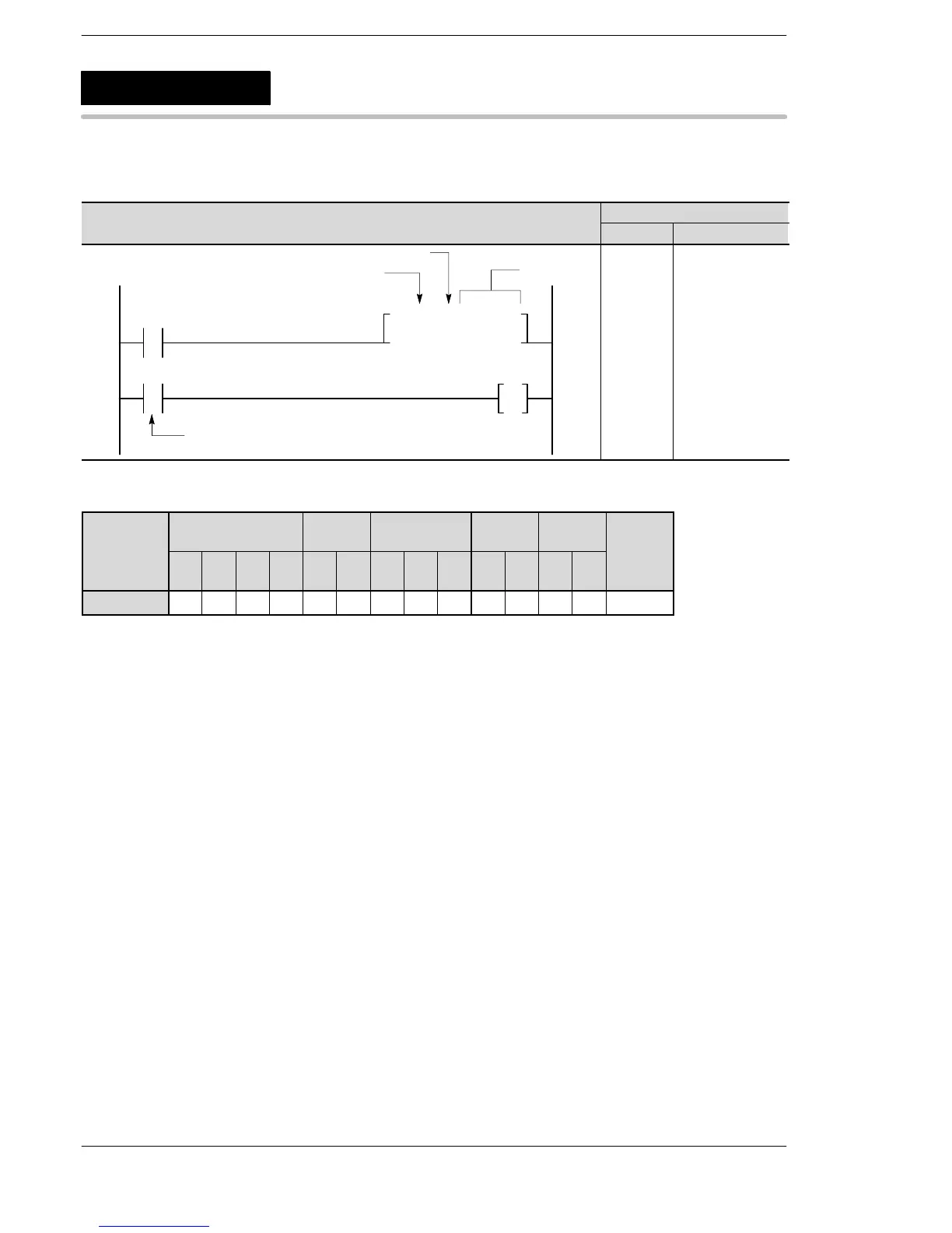
An OT instruction can appear immediately after a timer coil.
TML
Timer (0.001s units)
A: Available
N/A: Not Available
 Loading...


