Relays, Memory Areas and Constants
1-4
FP−e
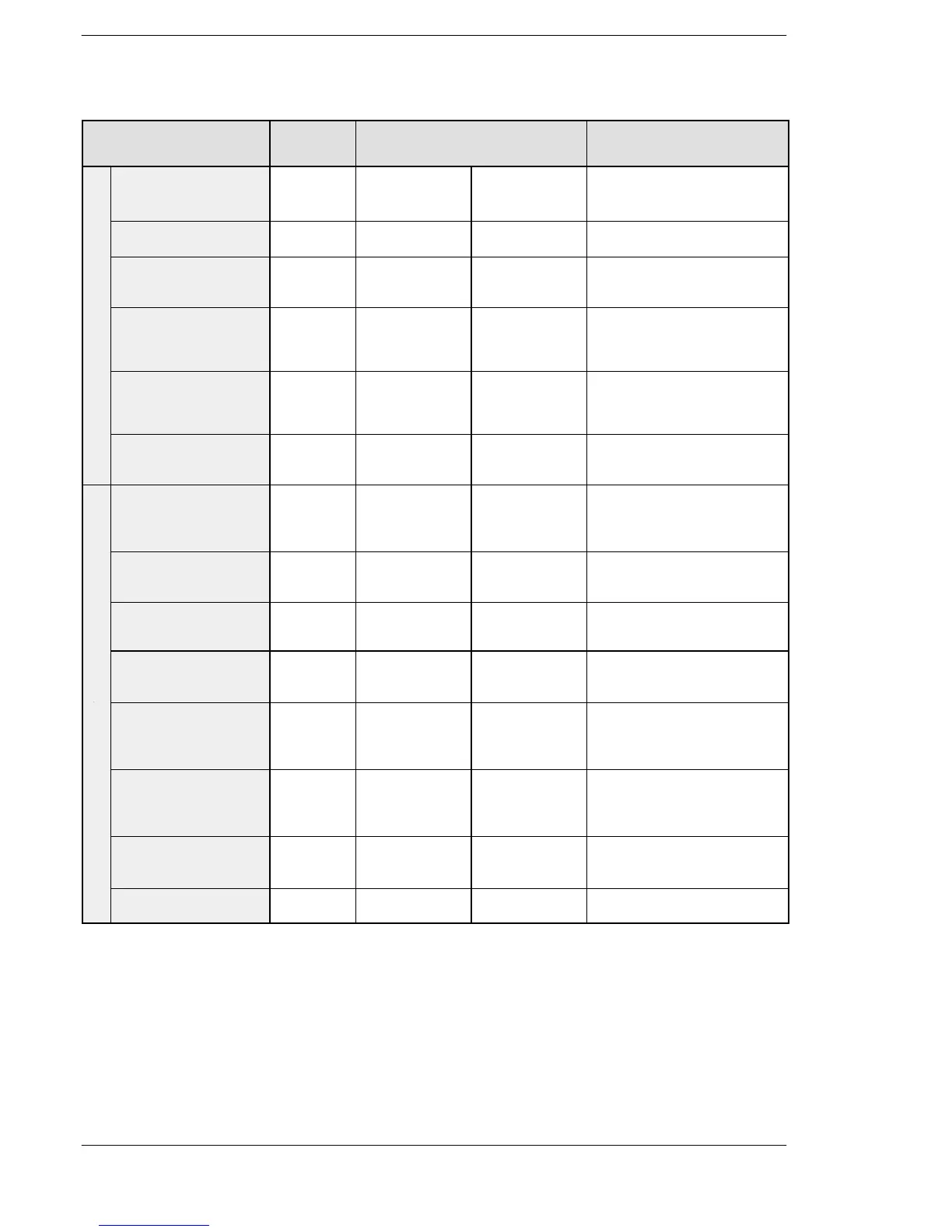
Item Number
of points
Memory area available for use
Matsushita IEC
Function
External input relay
(see note 3)
208 X0−X12F %IX0.0−
%IX12.15
Turns on or off based on
external input.
External output relay
(see note 3)
208 Y0−Y12F %QX0.0−
%QX12.15
Outputs on or off state
externally.
Internal relay
(see note 2)
1008 R0−R62F %MX0.0−
%MX0.62.15
Turns on or off only within a
program.
Relay
Timer
(see notes 1 and 2)
100 T0−T99/
C100−C143
%MX1.0−
%MX1. 99/
%MX2.100−
%MX2.143
Turns on when the timer reaches
the specified time.
Corresponds to the timer
number.
Counter
(see notes 1 and 2)
44 C100−C143/
T0−T99
%MX2.100−
%MX2.143/
%MX1.0−
%MX1.99
Turns on when the counter
increments.
Corresponds to the counter
number.
Special internal relay 64 R9000−R903F %MX0.900.0−
%MX0.903.15
Turns on or off based on specific
conditions. Used as a flag.
External input relay
(see note 3)
13 words WX0−WX12 %IW0−
%IW12
Code for specifying 16 external
input points as one word (16
bits) of data.
External output relay
(see note 3)
13 words WY0−WY12 %QW0−
%QW12
Code for specifying 16 external
output points as one word (16
bits) of data.
Internal relay
(see note 2)
63 words WR0−WR62 %MW0.0−
%MW0.62
Code for specifying 16 internal
relay points as one word (16
bits) of data.
Timer/counter set
value area
144 words SV0−SV143 %MW3.0−
%MW3.143
Data memory for storing a target
value of a timer and an initial
value of a counter. Stores by
timer/counter number.
Memo
Timer/counter elapsed
value area (see note 2)
144 words EV0−EV143 %MW4.0−
%MW4.143
Data memory for storing the
elapsed value during operation
of a timer/counter. Stores by
timer/counter number.
Special data
register
112 words DT9000−
DT9111
%MW5.9000−
%MW5.9111
Data memory for storing
specific data. Various settings
and error codes are stored.
Index register 2 words IX−IY %MW6.0−
%MW6.1
Used as an address of memory
area and constants modifier.