Connection to Input DevicesFP0 A/D Converter Unit
2 − 3
2.1 Wiring
2.1 Wiring
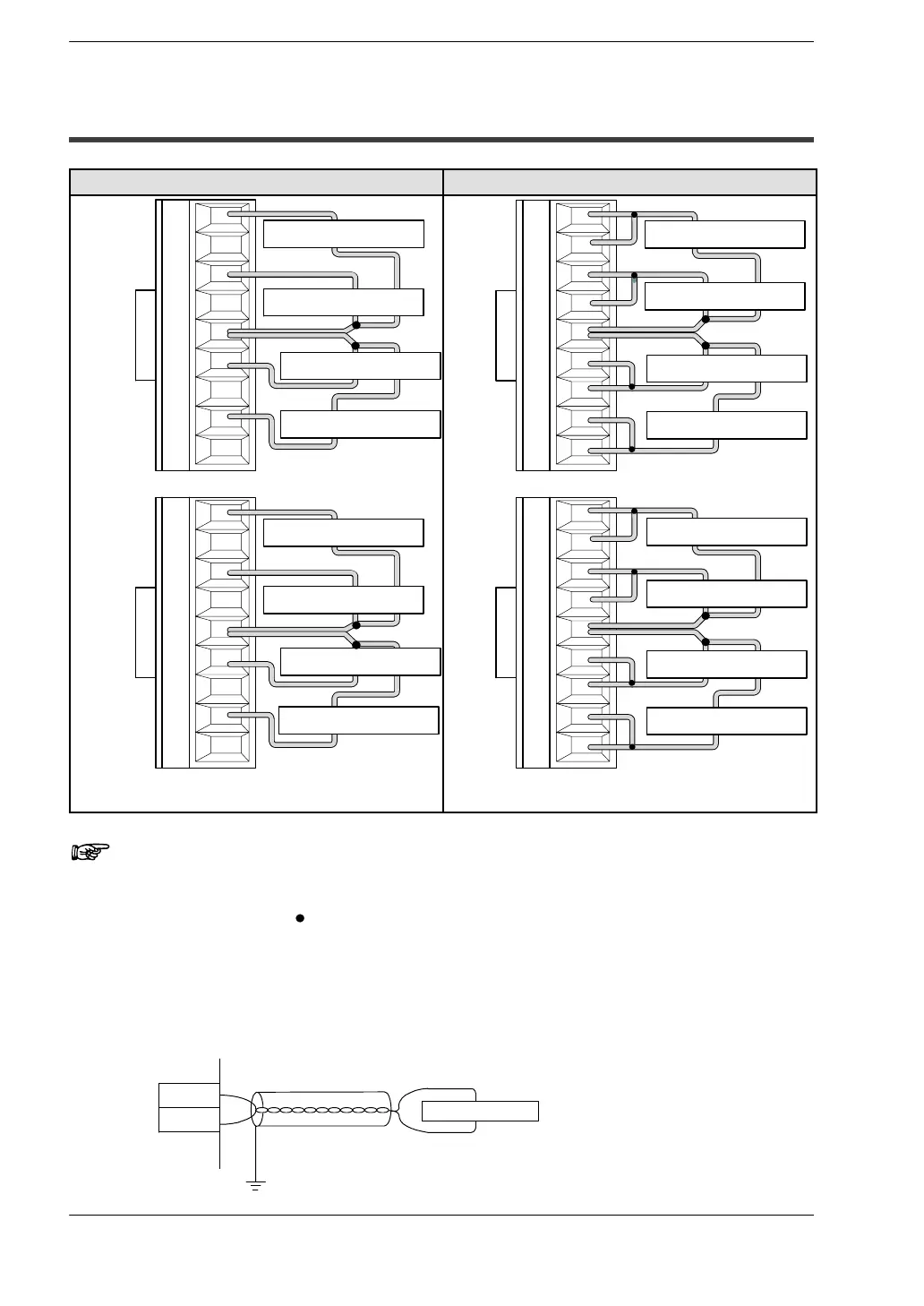
Voltage input Current input
V0
I0
COM
V1
I1
V2
I2
V3
I3
V4
I4
COM
V5
I5
V6
I6
V7
I7
Input instrument (ch0)
Input instrument (ch1)
Input instrument (ch2)
Input instrument (ch3)
Input instrument (ch4)
Input instrument (ch5)
Input instrument (ch6)
Input instrument (ch7)
V0
I0
COM
V1
I1
V2
I2
V3
I3
V4
I4
COM
V5
I5
V6
I6
V7
I7
Input instrument (ch0)
Input instrument (ch1)
Input instrument (ch2)
Input instrument (ch3)
Input instrument (ch4)
Input instrument (ch5)
Input instrument (ch6)
Input instrument (ch7)
Connect input instrument between V terminal and COM
terminal.
First, connect both V terminal and I terminal. And then
connect input instrument between it and COM terminal.
Notes
• Tie the COM connectors for two channels together as indicated by the
black circles (“
”) in the diagram above so that no more than two
wires go to each COM terminal.
• The two COM terminals are connected internally.
• We recommend that you use dual−core twisted pair shielded wiring
for the analog input wiring, and that you connect the shield to earth.
V
COM
Input instrument