Input Range SettingFP0 A/D Converter Unit
3 − 3
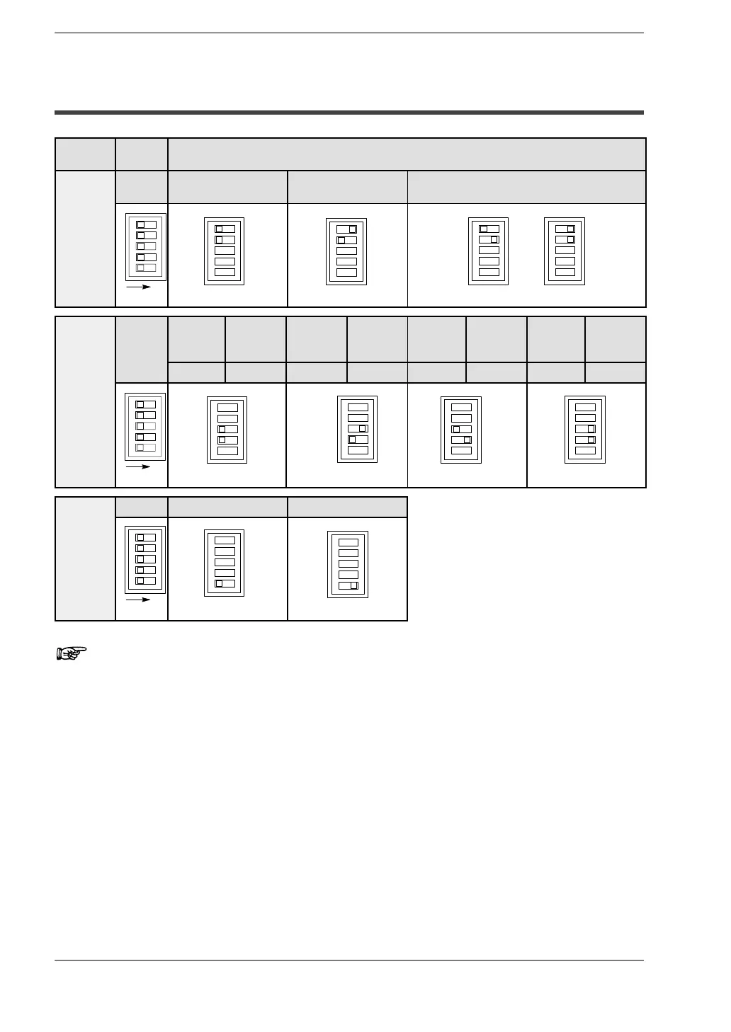
3.1 Input Range Setting Switch
3.1 Input Range Setting Switch
Mode Switch
number
Range
Analog
input
1 and 2
0to5V
0 to 20mA *1
−10 to 10V −100 to 100mV
range
1
2
ON
or
Number
of input
channels
3 and 4
Conver-
sion
channel
Number
of input
channels
Conver-
sion
channel
Number
of input
channels
Conver-
sion
channel
Number
of input
channels
Conver-
sion
channel
Number
of input
channels
ch0 and 1 2 ch0 to 3 4 ch0 to 5 6 ch0 to 7 8
3
ON
4
Averaging
5
No averaging ∗2 with averaging ∗3
function
ON
5
Notes
• (∗1) It is possible to use the 0 to 5V range and 0 to 20mA range
together.
• (∗2) The A/D conversion data is set for the specified input c onta ct point
area for each A/D conversion, on each channel.
• (∗3) On each channel, for each A/D conversion, the maximum and
minimum values from the data of the last ten times are excluded, and
the data from the other eight times is averaged, and the result set.
(Use when the environment contains much noise.)
• The switch reads only once when the power supply of FP0 control
unit is turned on.