I/O Allocation and ProgramFP0 A/D Converter Unit
6 − 3
6.1 I/O Number of A/D Converter Unit
6.1 I/O Number of A/D Converter Unit
I/O number of A/D converter unit
FP0 Control unit
WX2
WX3
WY2
WY3
WX4
WX5
WY4
WY5
WX6
WX7
WY6
WY7
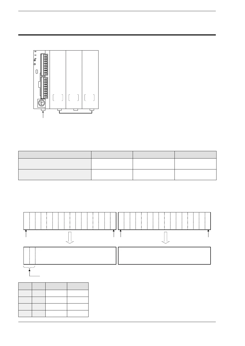
A combined maximum of three A/D converter
units and other expansion units can be con-
nected to one control unit. WX and WY are
allocated two words each (2 x 16 bits each).
First
expansion
Second
expansion
Third
expansion
With the setup illustrated in the diagram on the above, the data for each channel is
allocated as I/O data as indicated in the table below.
A/D converter unit input channel First expansion Second expansion Third expansion
ch0, 2, 4, 6
(Each 16 points)
WX2
(X20 to X2F)
WX4
(X40 to X4F)
WX6
(X60 to X6F)
ch1, 3, 5, 7
(Each 16 points)
WX3
(X30 to X3F)
WX5
(X50 to X5F)
WX7
(X70 to X7F)
Example of I/O allocation
Allocation of each channel’s conversion data and WX2 and WX3 when this unit is
connected to the first expansion.
X
3
F
X
3
E
X
3
D
X
3
C
X
3
B
X
3
A
X
3
9
X
3
8
X
3
7
X
3
6
X
3
5
X
3
4
X
3
3
X
3
2
X
3
1
X
3
0
X
2
F
X
2
E
X
2
D
X
2
C
X
2
B
X
2
A
X
2
9
X
2
8
X
2
7
X
2
6
X
2
5
X
2
4
X
2
3
X
2
2
X
2
1
X
2
0
Bit F
A
1
A
0
Conversion data of ch1, 3, 5, 7
(14 bit with sign)
Conversion data of ch0, 2, 4, 6
(16 bit with sign)
Conversion data switch flag
Bit 0
Bit F
Bit 0
A1 A0 WX3 WX2
0 0 ch1 data ch0 data
0 1 ch3 data ch2 data
1 0 ch5 data ch4 data
1 1 ch7 data ch6 data