FP0 A/D Converter Unit
Parts and Terminology
1 − 4
1.2 Analog Input Terminal Block
1.2 Analog Input Terminal Block
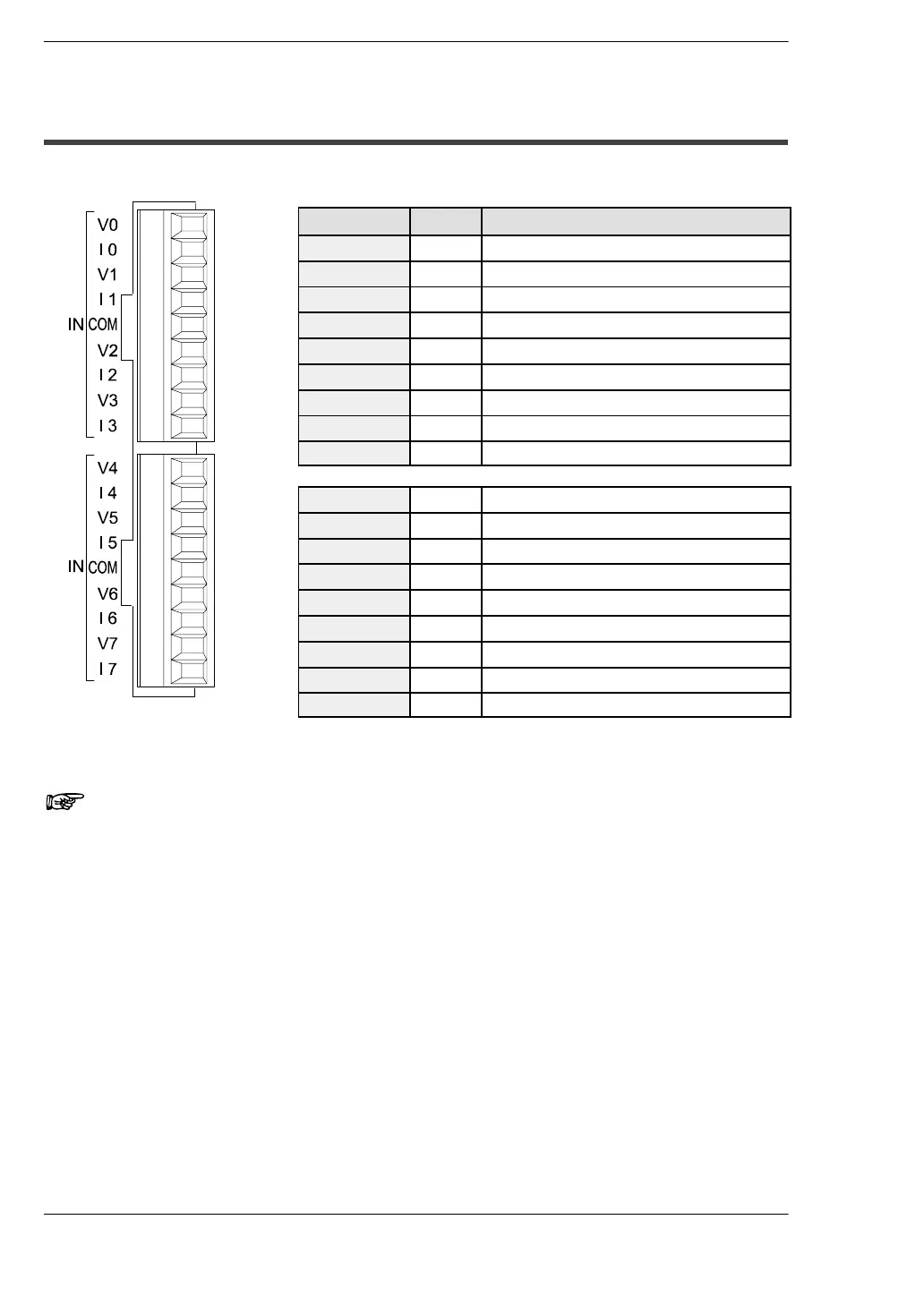
Pin number Name Description
1 V0 Analog input channel 0, voltage input
2 I0 Analog input channel 0, current input
3 V1 Analog input channel 1, voltage input
4 I1 Analog input channel 1, current input
5 COM Analog input, input common
6 V2 Analog input channel 2, voltage input
7 I2 Analog input channel 2, current input
8 V3 Analog input channel 3, voltage input
9 I3 Analog input channel 3, current input
1 V4 Analog input channel 4, voltage input
2 I4 Analog input channel 4, current input
3 V5 Analog input channel 5, voltage input
4 I5 Analog input channel 5, current input
5 COM Analog input, input common
6 V6 Analog input channel 6, voltage input
7 I6 Analog input channel 6, current input
8 V7 Analog input channel 7, voltage input
9 I7 Analog input channel 7, current input
Notes
• When the analog input is a current signal, short the V and I input pins
externally.
• The two COM terminals are connected internally.