9
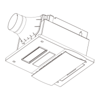
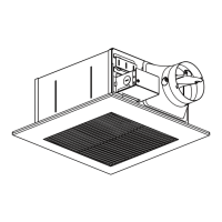
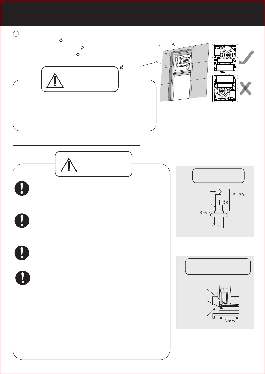
Properly install the main body according to the
direction indicating label on the main body.
Otherwise, it may cause electric leakage.
Fix the main body onto the window frame with the
supplied four 4×25 self-tapping screws.
使用附件包所提供的4顆 4×25的自攻螺絲,將機體
固定於窗膽。
請按照機體上的方向指示標籤,正確安裝產品。
否則可能會導 致漏電。
Installation direction
自攻螺絲
4×25
安裝方向
4×25 self-tapping screws
Strand the core wire together after stripping,
then insert them into about 8 mm deep position
of the terminal block, ensuring that the part is
under the spring slice, and no copper core cord is
exposed outside. Make sure that the copper core
cords are fixed by screws reliably (the
.
recommended screw fixing torque is 0.49 N m)
(See Figure 2). Otherwise an electric shock may
be caused.
先將剝線後分散的銅芯線絞合在一起,然後伸入到端子
台約8 mm深,並確保其在彈簧片的下方,切勿出現銅
線外露現象。螺釘擰緊後,請確保銅線不易鬆脫(建議
.
螺釘鎖緊扭矩為0.49 N m),否則可能會導致觸電。
(右圖2)
3. Connecting power cord
電源線的連接
電源線的絕緣膠不能破損,否則可能會導致觸電或短路。
剝線長度,請按照剝線示意圖(右圖1)進行剝線,如剝線
過長,可能會導致產品短路。
電源線請選用60227 IEC 53(RVV)型軟線,導線的截
2
面積為3×1.5 mm 。
For the stripping length, please according to the
wiring sketch (refer to figure 1). If the stripping
length is too long, it may cause short circuit.
Wiring sketch
Terminal cutaway view
Conductor
Conductor
Insulation
Figure 2
Figure 1
Spring slice
Earth
Power cord
98±1
Do not damage the sheath of the power cord,
otherwise an electric shock may be caused or
short circuit.
Please select 60227 IEC 53(RVV)ordinary
polyvinyl chloride sheathed cord. Nominal
2
cross-sectional area of conductors is 3×1.5 mm .
警告
WARNING
剝線示意圖
接線柱剝面圖
Unit:mm
單位:mm
電源線
接地引線
銅芯線
銅芯線
絕緣膠
彈簧片
(圖2)
(圖1)
警告
WARNING
安裝方法
HOW TO INSTALL
5
 Loading...