2
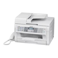
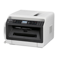
KX-MB2230JT/ KX-MB2270JT/ KX-MB2515JT/ KX-MB2545JT/ KX-MB2575JT/ DP-MB310JT
TABLE OF CONTENTS
PAGE PAGE
1 Safety Precautions -----------------------------------------------6
1.1. For Service Technicians ----------------------------------6
1.2. AC Caution---------------------------------------------------6
1.3. Personal Safety Precautions ----------------------------7
1.3.1. Moving Sections of the Unit-------------------------7
1.3.2. Live Electrical Sections ------------------------------7
1.4. Service Precautions ---------------------------------------7
1.4.1. Precautions to Prevent Damage from
Static Electricity ----------------------------------------7
2Warning--------------------------------------------------------------8
2.1. About Lead Free Solder (PbF: Pb free) --------------8
2.1.1. Suggested PbF Solder -------------------------------8
2.2. Discarding of P. C. Board --------------------------------9
2.3. Insulation Resistance Test -------------------------------9
2.4. Battery Caution ---------------------------------------------9
2.5. Laser Beam and Fuser Unit Section ------------------9
2.6. Note for Repairing---------------------------------------- 10
3 Specifications ---------------------------------------------------- 11
4 General/Introduction ------------------------------------------- 14
4.1. Accessory information ---------------------------------- 14
4.2. Translation Lists ------------------------------------------ 14
4.2.1. Report messages------------------------------------ 14
4.2.2. General messages ---------------------------------- 15
4.2.3. Interface messages --------------------------------- 16
5Features------------------------------------------------------------ 17
5.1. General Features----------------------------------------- 17
5.2. Hardware Requirements for Multi-Function
Software ---------------------------------------------------- 17
6 Technical Descriptions---------------------------------------- 18
6.1. Connection Diagram------------------------------------- 18
6.2. General Block Diagram--------------------------------- 19
6.3. Main Board Section-------------------------------------- 22
6.3.1. Data Flow---------------------------------------------- 22
6.3.2. RTC Backup Circuit ------------------------------- 32
6.3.3. Modem Circuit Operation ( Fax supported
models only ) ----------------------------------------- 32
6.3.4. TEL Line Section ( Fax supported models
only ) --------------------------------------------------- 33
6.4. NCU Section ( Fax supported models only ) ----- 35
6.4.1. General ------------------------------------------------ 35
6.4.2. EXT. TEL. Line Relay (RLY100) ----------------- 35
6.4.3. Bell Detection Circuit ------------------------------- 35
6.4.4. Remote FAX Activation Circuit ------------------- 35
6.4.5. TAM Interface Circuit ------------------------------- 35
6.5. ITS (Integrated telephone System) and
Monitor Section ( Fax supported models only )
---------------------------------------------------------------- 36
6.5.1. General ------------------------------------------------ 36
6.6. CIS Control Section-------------------------------------- 37
6.7. Motor Drive Section-------------------------------------- 38
6.7.1. Main Motor Control Circuit ------------------------ 38
6.7.2. Scanner motor drive circuit ----------------------- 40
6.7.3. Timing Chart and Wave Form of Motors------- 43
6.8. Timing chart and wave form of scanner
motors ------------------------------------------------------ 48
6.8.1. Drive mode of FB and ADF motor--------------- 48
6.8.2. 2 phase excitation ----------------------------------- 49
6.8.3. Normal torque 1-2 phase excitation (half
step) --------------------------------------------------- 50
6.8.4. Flat torque 1-2 phase excitation (half step)
----------------------------------------------------------- 51
6.8.5. W 1-2 phase excitation (Quarter step) -------- 52
6.8.6. 2W1-2 phase excitation --------------------------- 53
6.9. FAN Motor Section -------------------------------------- 54
6.9.1. General ------------------------------------------------ 54
6.9.2. Circuit Diagram of FAN ---------------------------- 54
6.9.3. Fan Control ------------------------------------------- 54
6.9.4. Control table------------------------------------------ 55
6.9.5. Waveform --------------------------------------------- 56
6.9.6. Abnormal Detect and Lock Protect Block----- 56
6.10. Solenoid Driver Section -------------------------------- 58
6.10.1. Optional Lower input Tray Motor (OPF
Motor) Drive and Solenoid Drive circuit ------- 60
6.11. LSU (Laser Scanning Unit) Section----------------- 64
6.12. Sensors and Switches Section----------------------- 66
6.12.1. Pick Up Sensor ------------------------------------- 67
6.12.2. Resist Sensor ---------------------------------------- 67
6.12.3. PTOP Sensor (Print timing Sensor) ----------- 68
6.12.4. ADU Sensor ------------------------------------------ 68
6.12.5. Exit Sensor ------------------------------------------- 69
6.12.6. Document Sensor----------------------------------- 69
6.12.7. Read Position Sensor------------------------------ 70
6.12.8. RADF JAM Sensor (Only for KX-MB25**
and DP-MB***)--------------------------------------- 71
6.12.9. MPT Sensor ----------------------------------------- 71
6.12.10. Paper Sensor ---------------------------------------- 72
6.12.11. CS open Sensor------------------------------------- 72
6.12.12. Rear door Sensor ----------------------------------- 73
6.12.13. Interlock switch -------------------------------------- 74
6.12.14. Toner Sensor----------------------------------------- 75
6.12.15. OPC Life Sensor Circuit--------------------------- 76
6.12.16. Toner Life Sensor Circuit-------------------------- 77
6.12.17. Drum and Toner Detetion ------------------------- 78
6.12.18. Power Switch ---------------------------------------- 80
6.13. Operation Board Section ------------------------------ 81
6.14. LCD Section----------------------------------------------- 82
6.15. HVPS (High Voltage Power Supply) Section ----- 84
6.15.1. HVPS Specification--------------------------------- 84
6.15.2. CHG-BIAS (Charge BIAS)/GRID/ UNIT------- 84
6.15.3. DEV DC BIAS UNIT-------------------------------- 85
6.15.4. DEV AC BIAS UNIT -------------------------------- 85
6.15.5. TRA (+) BIAS (Transfer (+) BIAS)/TRA (-)
BIAS (Transfer (-) BIAS) UNIT------------------- 85
6.16. Heat Lamp Control Circuit----------------------------- 86
6.17. Power Saving (Sleep) Function ---------------------- 91
6.18. Main Board Power Supply Section------------------ 92
6.18.1. 3.3V and 1.2V Power Supply Descriptions --- 92
6.18.2. 5V Power Supply Descriptions ------------------ 92
6.18.3. 24V Power Supply Descriptions----------------- 93
6.18.4. 2.5V Power Supply Descriptions---------------- 93
6.18.5. Main Unit Power Supply Condition ------------- 93
6.18.6. Main Unit Power Supply Sequence ------------ 94
6.18.7. Wave Form ------------------------------------------- 94
6.19. Power Supply Board Section ------------------------- 95
6.20. Mechanical Operation ---------------------------------- 96
 Loading...


