Do you have a question about the Panasonic KX-MB772CX and is the answer not in the manual?
Precautions for repair service and handling static electricity.
Safety precautions related to AC power connection and grounding.
Warnings about moving parts and live electrical sections.
Precautions to prevent damage from static electricity.
Information and cautions regarding the use of lead-free solder.
Procedure for checking insulation resistance for shock hazard prevention.
Cautionary notes on battery replacement and disposal of lithium batteries.
Warnings about laser radiation and the hot fuser unit.
List of optional accessories available for the unit.
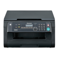
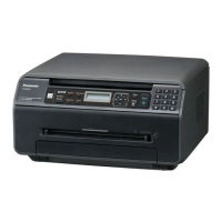
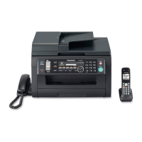
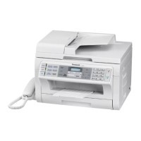
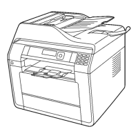
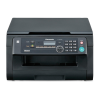
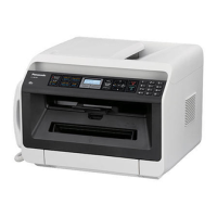
Overview of the unit's main functionalities and capabilities.
Specifies the hardware needed to run the multifunction software.
Diagram showing electrical connections within the unit.
High-level block diagram illustrating unit's functional blocks.
Detailed description of the main circuit board.
Details of the operation board, including LCD and keys.
Explanation of the LCD display functionality and its interface.
Description and specifications of the High Voltage Power Supply unit.
Circuit description for controlling the heat lamp in the fuser unit.
List of test codes for performing functional checks on the unit.
Table of service functions, codes, and their settings for KX-MB772CX.
Table of service functions, codes, and their settings for KX-MB262CX.
Details on memory clearing procedures and their effects.
Example output of user mode settings and system setup list.
Example of a printed service mode settings list.
Troubleshooting flowchart for Call Service 2 (LSU signal detection failure).
Troubleshooting for print quality issues.
Troubleshooting for paper feed issues.
Troubleshooting steps when the unit fails to initialize upon startup.
Troubleshooting for the operation panel.
Troubleshooting for various sensors.
Troubleshooting for motor issues.
Troubleshooting USB connectivity issues.
Procedure for clearing document jams in the Auto Document Feeder.
Procedures for clearing paper jams inside the unit.
Explanation of the fixing process and its components.
Procedures for replacing flat package ICs.
Troubleshooting procedures for main board issues preventing system boot-up.
General notes and guidance for using schematic diagrams.
Schematic diagram for the KX-MB262CX Main Board.
Layout diagram of the Flatbed Relay Board.
Layout diagram of the ADF Sensor Board (KX-MB772CX).
Layout diagram of the Handset Relay Board (KX-MB772CX).
Identification of cabinet, mechanical, and electrical parts.
List of parts for the KX-MB772CX Main Board.
List of parts for the KX-MB262CX Operation Board.
List of parts for the KX-MB772CX Operation Board.
List of parts for sensor boards.
| Type | All-in-One Printer |
|---|---|
| Functions | Print, Copy, Scan, Fax |
| Print Technology | Laser |
| Print Resolution | 1200 x 1200 dpi |
| Scanner Type | Flatbed |
| Optical Scan Resolution | 600 x 600 dpi |
| Paper Size | A4, Letter, Legal |
| Paper Capacity | 250 sheets |
| USB Version | USB 2.0 |
| Display | LCD |
| Duplex Printing | Manual |
| Copy Resolution | 600 x 600 dpi |
| Connectivity | USB, Ethernet |