Items
Adjustment
Point
Procedure Check
Repla
Part
(O)
*
Receive Audio
Check and
Confirmation
TP15
1. Configure the DECT tester (CMD60) as follows;
<Setting>
-Test mode: PP
-Mode: Nomal
-RFPI: 0102030405
2. Execute the command "testmode".
3. Execute the command "regcmd60"
4. Initiate connection from DECT tester.
5. Execute the command "openaudio".
6. Confirm that the value of EEPROM address "F3F" is "02". (If the value is not "02 (by
User)", set "02" and power off and power on, and return to clause 2.)
7. Input audio signal (50mVrms/1kHz tone) from DECT tester.
<DECT tester setting>
-Scramble: On
-AF Gen to ADPCM: On
-AF Meter Input: AF Voltm
-AF Gen Frequency: 1000Hz
-AF Gen Level: 50mVrms
8. Confirm hearing tone: 300mV ± 250mV (Just check Audio path)
9. Confirm that the audio distortion with DECT tester is < 5 %.
IC1, C
C31
R17, R
C10
C11,
D6,
IC3, C
C66
C60,
C57
C55, C
C62
R23, R
C63
C64, C
R1
(P)
Transmit Audio
Check and
Confirmation
TP15
1. Configure the DECT tester (CMD60) as follows;
<Setting>
-Test mode: FP
-Mode: Normal
-RFPI: 0102030405
2. Execute the command "testmode".
3. Execute the command "regcmd60".
4. Initiate connection from DECT tester.
5. Execute the command "openaudio".
6. Confirm that the value of EEPROM address "F3F" is "02". (If the value is not "02 (by
User)", set "02" and power off and power on, and return to clause 2.)
7. Input audio signal (30mVrms/1kHz tone) to DECT tester.
<DECT tester setting>
-Scramble: On
-AF Gen to ADPCM: Off
-AF Meter Input: ADPCM
-AF Gen Frequency: 1000Hz
-AF Gen Level: 30mVrms
8. Confirm hearing tone: 300mV ± 250mV (Just check Audio path)
9. Confirm that the audio distortion with DECT tester is < 5 %.
IC1,
R7,
R8, C6,
C5, R5,
C4, I
C54
C66, C
L3,
C57, C
C56
C62, R
R24
C63, C
C65
R1
Note:
After the measuring, sock up the solder of TP.
* :
PC Setting () is required beforehand.
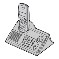
The connection of adjustment equipment are as shown in
Adjustment Standard (Handset) ().
15.2. Adjustment Standard (Handset)
When connecting the Simulator Equipments for checking, please refer to below.
Note:
49
www.freeservicemanuals.info
Digitized in Heiloo, Holland
 Loading...