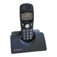
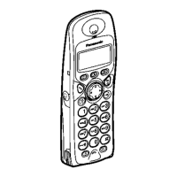
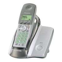
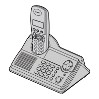
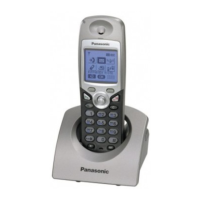
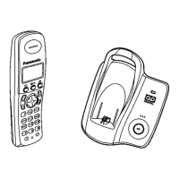
BASE UNIT HANDSET
Channel No Transmit Frequency
Receive Frequency
Transmit Frequency Receive Frequen
1 1897.344 1897.344 1897.344 1897.344
2 1895.616 1895.616 1895.616 1895.616
3 1893.888 1893.888 1893.888 1893.888
4 1892.160 1892.160 1892.160 1892.160
5 1890.432 1890.432 1890.432 1890.432
6 1888.704 1888.704 1888.704 1888.704
7 1886.976 1886.976 1886.976 1886.976
8 1885.248 1885.248 1885.248 1885.248
9 1883.520 1883.520 1883.520 1883.520
10 1881.792 1881.792 1881.792 1881.792
Note:
Channel No. 10: In the Test Mode on Base Unit and Handset.
19. BLOCK DIAGRAM (BASE UNIT)
20. CIRCUIT OPERATION (BASE UNIT)
20.1. Outline
Base Unit consists of the following ICs as shown in BLOCK DIAGRAM (BASE UNIT) ().
- DECT BBIC (Base Band IC): IC2
- Handling all the audio, signal and data processing needed in a DECT
base unit
- Controlling the DECT specific physical layer and radio section (Burst M
odule Controller section)
- ADPCM codec filter for speech encoding and speech decoding (DSP
section)
- Echo-cancellation and Echo-suppression (DSP section)
- Any tones (tone, sidetone, ringing tone, etc.) generation (DSP section)
- DTMF receiver (DSP section)
- Clock Generation for RF Module
- ADC, DAC, timer, and power control circuitry
- All interfaces (ex: RF module, EEPROM, LED, Analog Front End, etc.)
- RF Module: IC3
- PLL Oscillator
- Detector
- Compress/Expander
- First/Second Mixer
52
www.freeservicemanuals.info
Digitized in Heiloo, Holland
 Loading...