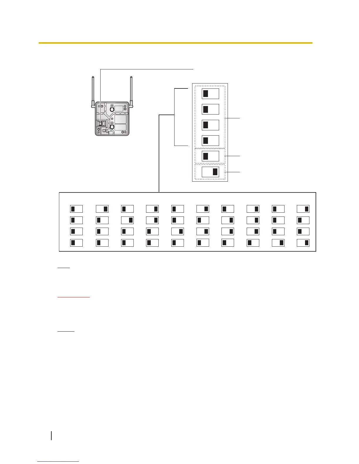
Channel Number Switch
Channel 1 Channel 2 Channel 3 Channel 4 Channel 5 Channel 6 Channel 7 Channel 8 Channel 9
1
2
3
4
1
2
3
4
1
2
3
4
1
2
3
4
1
2
3
4
1
2
3
4
1
2
3
4
1
2
3
4
1
2
3
4
DIP Switch
1
2
3
4
5
6
OFF ON
Radio Signal
Test Switch
Channel 0
1
2
3
4
Keep this switch at the default
"OFF" position. Otherwise, the
CS will not function.
Note
If more than 1 CS is in Radio Signal Test mode, each CS must have a unique channel number.
4. After setting the
DIP switches, connect the CS to an AC adaptor/battery box using a power supply adaptor.
WARNING
The AC adaptor
should be connected to a vertically oriented or floor-mounted AC outlet. Do not
connect the AC adaptor to a ceiling-mounted AC outlet, as the weight of the adaptor may cause
it to become disconnected.
Notice
• For users in the United Kingdom:
240 V AC must not be used on a building site. Instead of an AC adaptor, connect a battery box to
the CS.
• If the Power Supply Select switch is set to ON in step 3, connect the CS to an AC adaptor/battery
box. If it is set to OFF, connect the CS to a DLC/DHLC card (KX-TDA0158CE only).
162 Installation Manual
2.8.4 Before Site Survey

 Loading...