Do you have a question about the Panasonic KX-TDA600BX and is the answer not in the manual?
Lists essential safety precautions before, during, and after servicing equipment.
Details the procedure for performing an insulation resistance test on the equipment.
Warns about the dangers of incorrect battery replacement and proper disposal.
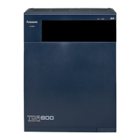
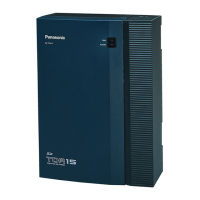
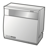
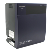
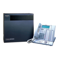
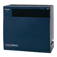
Explains the components of the basic system and how to expand it.
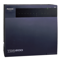
Details the maximum number of trunk and extension ports supported by different system configurations.
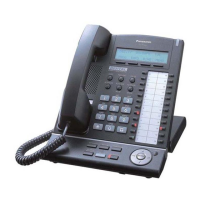
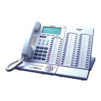
Details the maximum number of terminal equipment units supported by the IP-PBX.
Explains how to calculate load figures and select the appropriate PSU for each shelf.
Presents a block diagram illustrating the system configurations and card connections.
Provides step-by-step instructions for disassembling the EMPR card.
Details the procedure for disassembling the back board and its covers.
Details the functions, configuration, and components of the EMPR card.
Details the functions, configuration, and operation ratings of the EMPR card.
Presents a detailed block diagram of the EMPR card.
Provides detailed descriptions of the CPU, ASIC, Memory, USB, and SD card blocks.
Troubleshooting flowchart for issues occurring during system startup.
Troubleshooting steps when the main alarm light (LED2:ALARM) is on.
Troubleshooting steps when the SD card access light does not flash.
Troubleshooting steps when the battery alarm indication light turns on.
Troubleshooting steps when the main alarm indication light flashes.
Troubleshooting steps when an option card fails to start up.
Troubleshooting steps when the call path cannot be established.
Troubleshooting steps when noise is created during a call.
Troubleshooting steps when paging does not connect.
Troubleshooting steps for USB connection issues.
Troubleshooting steps for RS-232C connection problems.
Troubleshooting steps for issues related to the SD card interface.
Provides step-by-step instructions for removing a flat package IC from a PCB.
Details the procedure for installing a new flat package IC onto a PCB.
Lists all replacement parts for the EMPR board, including ICs, transistors, diodes, and connectors.
| Type | Hybrid IP-PBX |
|---|---|
| VoIP Support | Yes |
| Power Supply | AC 100-240 V, 50/60 Hz |
| Maximum IP Extensions | Up to 640 |
| Operating Temperature | 0°C to 40°C |
| Humidity | 10% to 90% (non-condensing) |
| Networking | IP Networking |
| Dimensions | 430 mm x 415 mm x 270 mm |