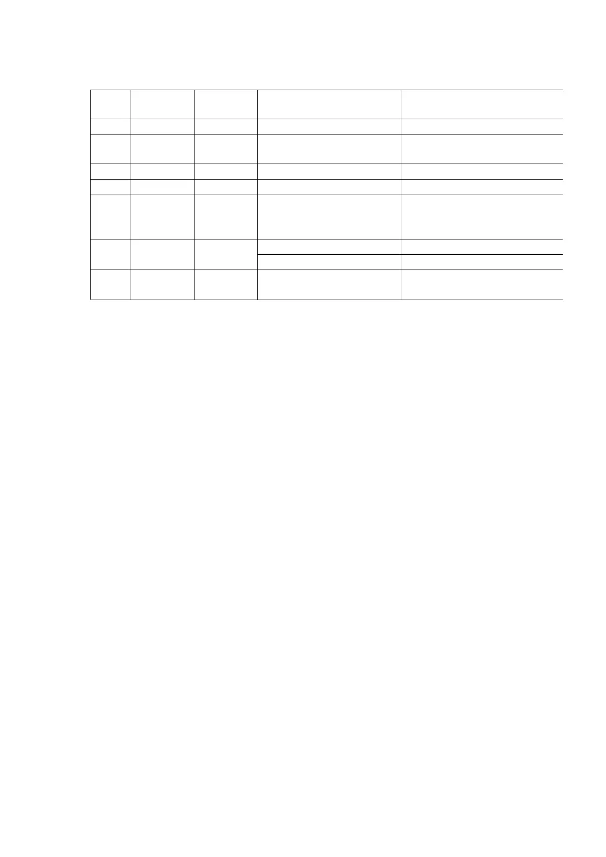
Ref.
No.
Procedure Shown in
Fig -.
To remove -. Remove -.
1 1 1 Lower Cabinet Screws (2.6 × 14)........(A) × 5
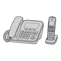
2 1, 2 2 Main P.C. Board Remove the Main P.C. Board
Remove the Flat Cable
3 1 ~ 3 3 Operation P.C. Board Screws (2.6 × 8).......(B) × 6
4 4
4
Battery Cover Remove the Battery Cover
5 4, 5 5 Rear Cabinet Screws (2.6 × 12).....(C) × 2
Screws (2 × 8)..........(D) × 2
Screw (2.6 × 12).......(E) × 1
6 4 ~ 6 6 Antenna Screw (2.6 × 12).......(F) × 1
Main P.C. Board Screws (2 × 8).....(G) × 4
7 4 ~ 7 7 Main P.C. Board Pull the Charge Terminals
Remove the Main P.C. Board
7. ASSEMBLY INSTRUCTIONS
7.1. Assembly the LCD to P.C. Board (Base Unit)
31
 Loading...