This document is a service manual for Panasonic's KX-TG4011AGT, KX-TG4012AGT, KX-TG4013AGT, and KX-TGA403AGT expandable digital cordless phones. It provides comprehensive information for service technicians, covering technical descriptions, specifications, operation, and maintenance.
Function Description
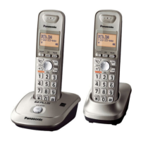
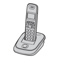
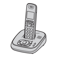
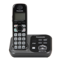
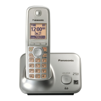
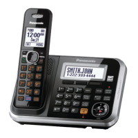
The devices are DECT 6.0 (Digital Enhanced Cordless Telecommunications 6.0) expandable digital cordless phones. They are designed to provide wireless telephone communication, supporting Caller ID functionality and offering expandability to multiple handsets. The system consists of a base unit, one or more handsets, and a charger unit for additional handsets. The base unit connects to the telephone line, while handsets communicate wirelessly with the base unit.
The core of the system's digital speech and signal processing, as well as memory management, is handled by the BBIC (Base Band IC) and EEPROM. The BBIC is fully controlled by a host processor, which manages functions like DTMF generation, Caller ID demodulation, digital switching for voice signals between the telephone line and handsets, and interfacing with RF parts, key scanning, and the telephone line. The EEPROM stores essential information such as message numbers, ID codes, flash times, and tone/pulse settings.
The telephone line interface circuit manages bell signal detection, ON/OFF hook and pulse dial functions, and side tone cancellation. It detects incoming ring voltages, provides off-hook conditions for active calls, and handles pulse dialing by controlling the Q141 transistor. The side tone circuit prevents the transmitted signal from feeding back into the received signal.
A parallel connection detect circuit and auto disconnect circuit are included to manage call waiting and stutter tone functions when other telephones are connected in parallel. This circuit monitors T/R voltage changes to determine if a parallel connection is on-hook or off-hook. If the auto disconnect function is enabled and a parallel connection is detected as off-hook, the BBIC disconnects the line.
Caller ID functionality is a key feature, allowing users to see calling party information. The system receives FSK (Frequency Shift Keying) modulated data from the telephone exchange between the first and second rings. This data includes information like time, telephone number, name, and data code. The system supports both single and plural message formats for Caller ID. For Call Waiting Caller ID (CIDCW), the system receives CAS and ACK signals, and FSK/MARK data to display calling party information during an existing call.
Important Technical Specifications
- Standard: DECT 6.0 (Digital Enhanced Cordless Telecommunications 6.0)
- Number of Channels: 60 Duplex Channels
- Frequency Range: 1.91 GHz to 1.93 GHz
- Duplex Procedure: TDMA (Time Division Multiple Access)
- Channel Spacing: 1,728 kHz
- Bit Rate: 1,152 kbit/s
- Modulation: GFSK (Gaussian Frequency Shift Keying)
- RF Transmission Power: 115 mW (max.)
- Voice Coding: ADPCM 32 kbit/s
- Base Unit Power Source: AC Adaptor (PQLV219AGY, 220-240 V AC, 50/60 Hz)
- Handset Power Source: Rechargeable Ni-MH battery, AAA (R03) size (1.2 V 550 mAh)
- Charger Power Source: AC Adaptor (PQLV219AGY, 220-240 V AC, 50/60 Hz)
- Operating Conditions: 0°C - 40°C, 20% - 80% relative air humidity (dry)
- Base Unit Dimensions (H x W x D): Approx. 54 mm x 98 mm x 121 mm
- Base Unit Mass (Weight): Approx. 110 g
- Handset Dimensions (H x W x D): Approx. 159 mm x 48 mm x 32 mm
- Handset Mass (Weight): Approx. 130 g
- Charger Unit Dimensions (H x W x D): Approx. 51 mm x 72 mm x 85 mm
- Charger Unit Mass (Weight): Approx. 60 g
- Operation Range: Up to 300 m outdoors, Up to 50 m indoors (depending on conditions).
- Analog Telephone Connection: Telephone Line
Usage Features
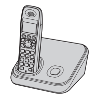
The phones are expandable, allowing registration of optional handsets (KX-TGA654AG) to a single base unit, supporting up to 6 handsets. The manual emphasizes that optional handsets may have different models and some functions might not be available, advising users to refer to individual operating instructions.
The manual includes instructions for:
- Registering a Handset: Handsets are pre-registered, but if needed, users can re-register by accessing the "Ajuste Padrão" and "Registrar Monof" menus on the handset and pressing the LOCATOR button on the base unit for about 5 seconds.
- Deregistering a Handset: Handsets can cancel their own registration or that of other handsets through the "Ajuste Padrão" and "Cancelar Regist" menus.
- Deregistering All Handsets by the Base Unit: Pressing and holding the LOCATOR/INTERCOM button on the base unit will erase all registration information from the base unit, though handset information will remain.
Maintenance Features
The service manual provides detailed instructions for troubleshooting, disassembly, assembly, and component replacement, specifically for service technicians.
- Troubleshooting Guide: A flowchart helps diagnose issues such as power problems, battery charge, link establishment, RF part functionality, handset transmission/reception, and Caller ID.
- Test Mode (Engineering Mode): This mode allows technicians to read and write EEPROM data, check addresses, and input new data for various settings. It includes warnings about potential unit damage if data is entered incorrectly.
- Measurements and Adjustments: This section details required equipment (DMM, oscilloscope, frequency counter, DECT tester), JIG cable connections for both base unit and handset, and batch file installation for PC-based adjustments. It outlines adjustment standards for base unit, charger unit, and handset, including checking voltages, frequencies, and RF signals.
- Component Replacement:
- Handset LCD Replacement: Detailed steps are provided for peeling off the Flexible Flat Cable (FFC), fitting a new LCD, and heat welding it with a soldering iron, emphasizing tolerance checks for vertical and horizontal intervals.
- Flat Package IC Replacement: Instructions cover preparation (PbF solder, soldering iron temperature, flux), removal (applying plenty of solder, cutting pins, removing melted solder), and installation (temporarily fixing, applying flux, sliding soldering iron).
- Shield Case Replacement: Steps include cutting the case along perforations, removing cut parts, cutting corners, removing remnants by melting solder, and then placing and soldering a new shield case.
- LLP (Leadless Leadframe Package) IC Replacement: Instructions detail preparation, caution for using hot air desoldering tools, removal (heating with hot air, picking up with tweezers), and cleaning the P.C. Board.
- Solder Bridge Removal: Techniques for lightly resoldering and removing excess solder with a soldering iron are described.
- Post-Replacement Procedures: After replacing ICs or X'tals, it is crucial to download required data (programming data, adjustment data) using specific commands and batch files via a PC connected with a JIG cable. This includes adjusting clock frequencies for both base unit and handset.
- Safety Precautions: The manual stresses that service information is for experienced repair technicians only, warning against potential dangers for non-technical individuals. It highlights the importance of using specified parts for critical components (marked by 'A' in diagrams) to prevent shock, fire, or other hazards, and advises against modifying the original design. Precautions for handling static-sensitive ICs and LSIs are also provided.
- Lead-Free Solder (PbF) Information: The manual notes that products manufactured with lead-free solder are marked "PbF" on the PCB. It recommends using PbF solder for service and repair, providing details on its higher melting point and precautions for soldering.
- Battery Caution: Warnings include the danger of explosion if batteries are incorrectly replaced, the need to use manufacturer-recommended types, and proper disposal of used batteries.
- Discarding P.C. Board: Users are advised to delete personal information (like telephone directory and caller list) or scrap the P.C. Board before discarding.