11
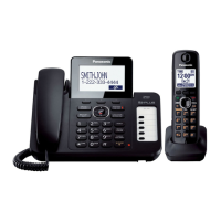
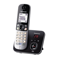
KX-TG6461BXT/KX-TGA641BXT
4.2.5. RF cuircuit
BBIC(IC501) inclueds the RF transceiver circuit. (LNA,Mixer, IF filter, modulator/Demodulator,PLL, VCO etc).
This RF transceiver is interfaced with Power-AMP(IC801) and Antenna circuit.
4.2.6. Pulse Dialling
During pulse dialling the hookswitch (Q3, Q4) is used to generate the pulses using the HOOK control signal, which is set high
during pulses. To force the line impedance low during the “pause” intervals between dial pulses, the PULSE_DIAL signal turns
on Q2.

 Loading...
