Do you have a question about the Panasonic KX-TG6671B and is the answer not in the manual?
Describes the product type and functionality.
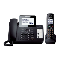
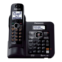
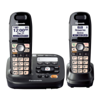
Details model variations and included components.
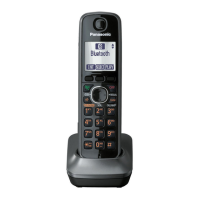
Information on expanding system capabilities with optional units.
Critical safety information for component replacement and product modification.
Guidelines and precautions for using lead-free solder.
Rules to prevent fires, injury, or electric shock during repair.
Measures to prevent damage to ICs and LSIs from static discharge.
Recommended lead-free solder wire sizes for service.
Procedure for safe disposal and data deletion from PCBs.
Key technical parameters like frequency range, channels, and modulation.
Table comparing Base Unit, Portable, and Charger specifications.
Explanation of the US-DECT frequency range and frame format.
Description of the Time Division Multiple Access system cycles and paths.
Schematic showing the main components and their interconnections.
Diagram illustrating the radio frequency components and signal paths.
Details on BBIC operations like voice messaging and caller ID.
Explains data storage in Flash Memory and EEPROM.
Describes how power supply voltages are generated and reset signals function.
Explains hook detection, off-hook conditions, and pulse dialing.
Details how the side tone circuit prevents signal feedback.
Explains detection of parallel connections and auto disconnect features.
Describes single and plural message formats for caller ID data.
Diagram showing the main ICs and connections within the portable unit.
Details portable power management and initialization sequence.
Explains the charging process for the portable unit.
Describes how low battery and power down are detected.
Detailed routes for various signals within the system.
Refers to operating instructions for component locations.
Directs users to operating instructions for setup and use.
Steps for entering and operating the base unit's engineering mode.
Instructions to reset portable user settings to factory defaults.
A step-by-step guide to diagnose and resolve common issues.
Steps to verify power supply and voltage levels in the base unit.
Steps to check battery and voltage status in the portable unit.
Troubleshooting steps for when the base unit fails to record messages.
Procedure to adjust auto disconnect for low-voltage lines.
Steps to verify proper playback functionality in the base unit.
Checks for portable and charger unit battery charging status.
Procedure to confirm normal link operation between base unit and portable.
Steps to ensure the portable can link correctly with the base unit.
Method to identify whether the base unit or portable is RF defective.
Flowchart for checking link, crystal, TX, and range confirmation.
Table detailing checks for link, crystal frequency, TX confirmation, and range.
Chart for setting TX power and checking RX sensitivity for range confirmation.
Instructions for pairing a portable with the base unit.
Steps to remove a portable's registration from the base unit.
Procedures to check portable transmit and receive functions.
Checks for base unit corded handset and speakerphone operation.
Step-by-step guide for taking apart the base unit.
Detailed instructions for disassembling the portable handset.
Guide for taking apart the charger unit.
Procedures for replacing the LCD on the base unit.
Detailed guide for replacing the LCD on the portable unit.
List of necessary tools for measurements and adjustments.
Instructions for connecting JIG cable and setting up PC for measurements.
Reference points and procedures for adjusting base unit parameters.
Reference points and procedures for adjusting charger unit parameters.
Reference points and procedures for adjusting portable unit parameters.
Steps for downloading data to EEPROM and adjusting X'tal on base unit.
Procedures for downloading data and adjusting clock on portable unit.
Table listing channel numbers and their corresponding frequencies.
Preparation and procedure for removing LLP ICs.
Guidelines for removing and installing flat package ICs.
Method for replacing the shield case on the PCB.
Pinout and terminal identification for base unit ICs and transistors.
Pinout and terminal identification for portable ICs and transistors.
Detailed circuit diagram for the base unit's main functionality.
Circuit diagrams for the portable unit's main, RF, and LED functions.
Circuit diagram for the charger unit.
Top view of the base unit's main PCB showing component placement.
Bottom view of the base unit's main PCB, showing solder side connections.
Component and bottom views of the base unit's operation PCB.
Top view of the portable's main PCB with component layout.
Bottom view of the portable's main PCB, showing solder side.
Top view of the charger unit's PCB showing component layout.
Bottom view of the charger unit's PCB.
Exploded diagram of base unit parts with reference numbers.
Exploded diagram of portable unit components and their assembly.
Exploded diagram of the charger unit components.
List and illustration of accessories included with the KX-TG6671B.
List and illustration of accessories included with the KX-TG6672B.
List and illustration of accessories included with the KX-TGA660B.
List of replacement parts for the base unit's external components.
List of replacement electronic components for the base unit PCB.
List of replacement parts for the portable unit's external components.
List of replacement electronic components for the portable unit PCB.
List of replacement parts for the charger unit's external components.
List of fixtures and tools required for service procedures.
| Number of Handsets | 1 |
|---|---|
| Expandable up to | 6 handsets |
| Frequency | 1.9 GHz |
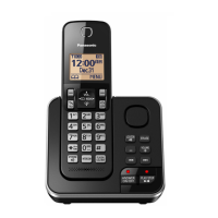
| Answering System | Yes |
| Recording Time | Up to 18 minutes |
| Caller ID | Yes |
| Call Waiting Caller ID | Yes |
| Speakerphone | Yes |
| Display | LCD |
| Backlit Display | Yes |
| Color | Black |
| Technology | Digital |
| Range | Up to 1000 feet |
| Power Source | Rechargeable battery |
| Type | Cordless Phone with Answering Machine |