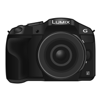
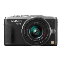
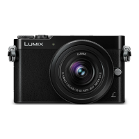
Do you have a question about the Panasonic LUMIX DMC-G6P and is the answer not in the manual?
| Brand | Panasonic |
|---|---|
| Model | LUMIX DMC-G6P |
| Category | Digital Camera |
| Language | English |
Provides essential guidelines for safe operation and maintenance procedures.
Details the procedure for performing a cold check of leakage current to ensure safety.
Outlines the method for conducting a hot check of leakage current for safety verification.
Explains the critical procedure for safely discharging the E.Capacitor on the Flash P.C.B.
Guides on preventing damage to sensitive electronic components from electrostatic discharge.
Provides information on the proper recycling of lithium-ion batteries in the USA.
Advises on safety precautions related to the AC cord for specific camera models.
Details important safety information concerning the AC cord and mains lead.
Provides specific cautions and instructions regarding the AC mains lead and plug.
Describes the procedure for safely replacing the lithium battery in the camera.
Provides an overview of the service manual's content and purpose.
Directs users to specific service manuals for maintenance of bundled lenses.
Highlights critical notices and recommendations for servicing the camera unit.
Covers service aspects specific to the camera body unit.
Details service information for the H-PS14042 interchangeable lens unit.
Provides service information for the H-FS1442A interchangeable lens unit.
Covers service aspects for the H-FS014042 interchangeable lens unit.
Details service information for the H-FS45150 interchangeable lens unit.
Provides service information for the H-FS14140 interchangeable lens unit.
Offers guidance on handling and cleaning flexible cables and connectors.
Contains important notes and considerations for servicing the camera.
Explains the functionality and service aspects of the Wi-Fi feature.
Highlights crucial notices for service personnel regarding data protection and customer information.
Explains the properties and usage of lead-free solder in electronic components.
Describes methods to identify camera model suffixes based on nameplate markings.
Describes methods to identify camera model suffixes based on nameplate markings.
Details the procedure for performing initial settings after component replacement.
Lists the technical specifications for the camera body unit.
Provides technical specifications for various interchangeable lenses.
Identifies and describes the controls and components on the camera body.
Illustrates and labels the controls and components of the interchangeable lenses.
Explains how to access and display stored error codes for troubleshooting.
Guides on initial inspection steps for body and lens issues before declaring them faulty.
Explains the tilt sensor function and the procedure for its adjustment.
Provides a flowchart for diagnosing failures related to the NFC function.
Covers troubleshooting steps and procedures for the Wi-Fi P.C.B.
Lists the necessary service fixtures and specialized tools for checking and servicing.
Recommends working in a specified clean environment for lens cleaning.
Describes the service position and extension cables used for checking and replacing parts.
Details the disassembly and assembly procedures for the camera body.
Presents a flowchart illustrating the sequence for disassembling the camera body.
Illustrates the physical locations of the various Printed Circuit Boards (PCBs) within the camera.
Provides step-by-step instructions for disassembling the camera body components.
Explains the procedure for removing the rear case unit of the camera body.
Details the steps for removing the main Printed Circuit Board (P.C.B.).
Guides on removing the top unit and the Flash Printed Circuit Board (P.C.B.).
Explains the procedure for removing the front case unit of the camera.
Details the steps required to remove the mount box unit from the camera.
Provides instructions for removing the NFC antenna unit.
Details the procedure for removing the Wi-Fi Printed Circuit Board (P.C.B.).
Explains how to remove the battery frame from the camera body.
Provides instructions for removing the battery door unit.
Details the steps for removing the battery lock knob.
Explains the procedure for removing the Live View Finder (LVF) unit.
Provides instructions for removing the LVF module.
Details the steps for removing the LVF lens unit.
Explains the procedure for removing the Microphone Printed Circuit Board (P.C.B.).
Provides instructions for removing the External Microphone Printed Circuit Board (P.C.B.).
Details the steps for removing the Hot Shoe Flexible Printed Circuit (FPC) Unit.
Explains the procedure for removing the flash lock lever.
Provides instructions for removing the hot shoe unit and microphone unit.
Details the steps for removing the flash unit from the camera.
Explains the procedure for removing the Hinge SW Flexible Printed Circuit (FPC) Unit.
Provides instructions for removing the LCD Interface P.C.B. and LCD Unit.
Details the steps for removing the Rear Operation Flexible Printed Circuit (FPC) Unit.
Directs users to specific manuals for the disassembly and assembly of bundled lenses.
Shows a matrix correlating replaced parts with necessary adjustment procedures.
Provides notices and instructions for the external cleaning of the camera body, sensor, and lens.
Presents the overall block diagram of the camera system.
Illustrates the system control block diagram of the camera.
Shows the first part of the video and audio processing block diagram.
Presents the second part of the video and audio processing block diagram.
Details the block diagram for the eye sensor, lens, and flash functionalities.
Illustrates the power supply block diagram for the camera system.
Provides a diagram showing the interconnection of various components and units.
 Loading...