45
8.3. Service Position
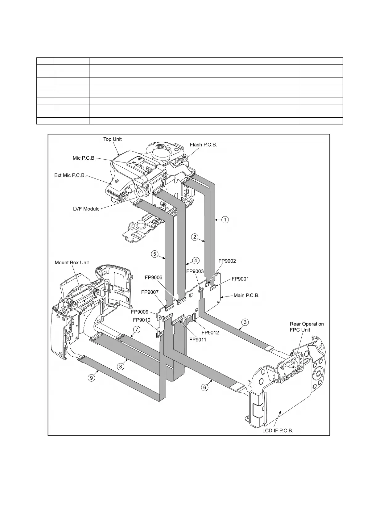
This Service Position is used for checking and replacing parts. Use the following Extension cables for servicing.
Table S1 Extension Cable List
CAUTION. (When servicing Flash P.C.B.)
1. Be sure to discharge the E.Capacitor on Flash P.C.B..
Refer to “How to Discharge the E.Capacitor on Flash P.C.B.”.
The E.Capacitor voltage is not lowered soon even if the AC Cord is unplugged or the battery is removed.
2. Be careful of the high voltage circuit on Flash P.C.B..
3. DO NOT allow other parts to touch the high voltage circuit on Flash P.C.B..
No. Parts No. Connection Form
1 RFKZ0564 FP9001(MAIN) ←→ TOP UNIT 23pin / 0.3 FFC
2 VFK1950 FP9002(MAIN) ←→ FLASH FPC - FP8502(FLASH P.C.B.) 33pin / 0.3 FFC
3 RFKZ0626 FP9003(MAIN) ←→ REAR OPERATION FPC UNIT 21pin / 0.3 FFC
4 RFKZ0619 FP9006(MAIN) ←→ LVF MODULE 61pin / 0.3 FFC
5 RFKZ0354 FP9007(MAIN) ←→ HOT SHOE FPC UNIT - FP4202(MIC P.C.B.)/ FP4401(EXT MIC P.C.B.) 37pin / 0.3 FFC
6 RFKZ0477 FP9009(MAIN) ←→ LCD HINGE UNIT - FP7201(LCD IF P.C.B.) 45pin / 0.3 FFC
7 RFKZ0564 FP9012(MAIN) ←→ MOUNT BOX UNIT 23pin / 0.3 FFC
8 RFKZ0619 FP9011(MAIN) ←→ MOUNT BOX UNIT 61pin / 0.3 FFC
9 RFKZ0583 FP9010(MAIN) ←→ MOUNT BOX UNIT 19pin / 0.3 FFC

 Loading...