Do you have a question about the Panasonic LUMIX DMC-G7KPP and is the answer not in the manual?
Special components for safety marked with A. Replace with specified parts to prevent hazards.
Measure resistance between plug and exposed metallic parts to check for short circuits.
Procedure to measure potential across resistor between exposed parts and ground.
Procedure to safely discharge the E.Capacitor on the Flash P.C.B. before disassembly.
Techniques to reduce component damage from static electricity.
Information on how to recycle lithium-ion batteries.
Step-by-step procedure for replacing the lithium battery.
Safety precautions and wiring instructions for the AC cord.
Explains the purpose and content of the service manual.
Refers to other service manuals for bundled lens disassembly and maintenance.
General important notices for servicing the camera body and lens.
Notes regarding Wi-Fi function and other service-related information.
Information on lead-free solder composition and usage for environmental conservation.
Method to identify model suffix based on safety registration marks on the nameplate.
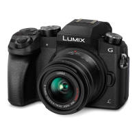
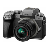
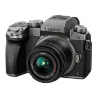
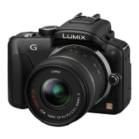
Identifies and describes the controls on the camera body.
Identifies and describes the controls on the interchangeable lenses.
Explains how to display and interpret error codes stored in memory.
Provides initial inspection tips before determining a unit is faulty.
Troubleshooting and password removal for the Wi-Fi circuit.
Lists and describes the service fixtures and tools required for checking and servicing the unit.
Recommends working in a clean environment for repair quality.
Instruction to perform adjustment after replacing the Main P.C.B. Unit.
Describes the service position and extension cables for checking and replacing parts.
Provides a disassembly flow chart and PCB locations for the camera body.
Refers to service manuals for disassembly and assembly of bundled lenses.
Relates replaced parts to necessary adjustments, referencing adjustment software.
Provides instructions for cleaning the camera body, image sensor, and LVF unit.
Refers to service manuals for maintenance of bundled lenses.
Provides a comprehensive block diagram of the camera's system architecture.
Details the system control logic and interconnections within the camera.
Illustrates the video and audio processing paths, including sensor and memory interfaces.
Shows video/audio processing connections for Wi-Fi, microphone, and external audio interfaces.
Depicts video/audio processing paths related to the LCD and LVF units.
Illustrates the block diagram for the lens unit, including motor drive and shutter control.
Shows the block diagram for the flash and hot shoe circuitry.
Details the power supply and voltage regulation for various camera components.
Illustrates the power control and DC/DC converter circuitry for camera operation.
Shows the interconnection of various PCBs and modules within the camera.
| Brand | Panasonic |
|---|---|
| Model | LUMIX DMC-G7KPP |
| Category | Digital Camera |
| Language | English |