40
8.4. Service Position
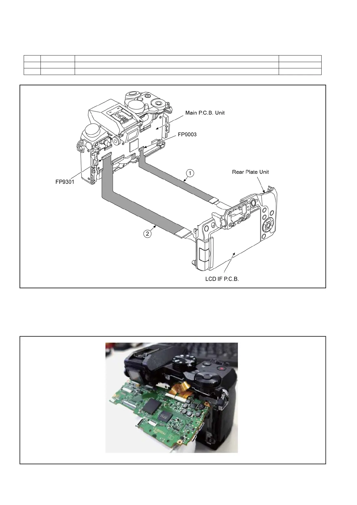
This service position is used for checking and replacing parts. Use the following extension cables for servicing.
Table S1 Extension Cable List
CAUTION. (When servicing Main P.C.B. Unit)
1. <Main P.C.B. Unit instructions>
• When removing the Main P.C.B. Unit, remove the E.Capacitor.
2. When checking except the Mount Box Unit, as shown in fig remove FP9008, FP3901 and FP9010, and check in a state of lift-
ing the Main P.C.B. Unit.
No. Parts No. Connection From
1 RFKZ0564 FP9003(MAIN)←→REAR PLATE UNIT 23pin / 0.3 FFC
2 RFKZ0477 FP9301(MAIN)←→LCD HINGE UNIT-FP7201(LCD IF P.C.B.) 45pin / 0.3 FFC

 Loading...