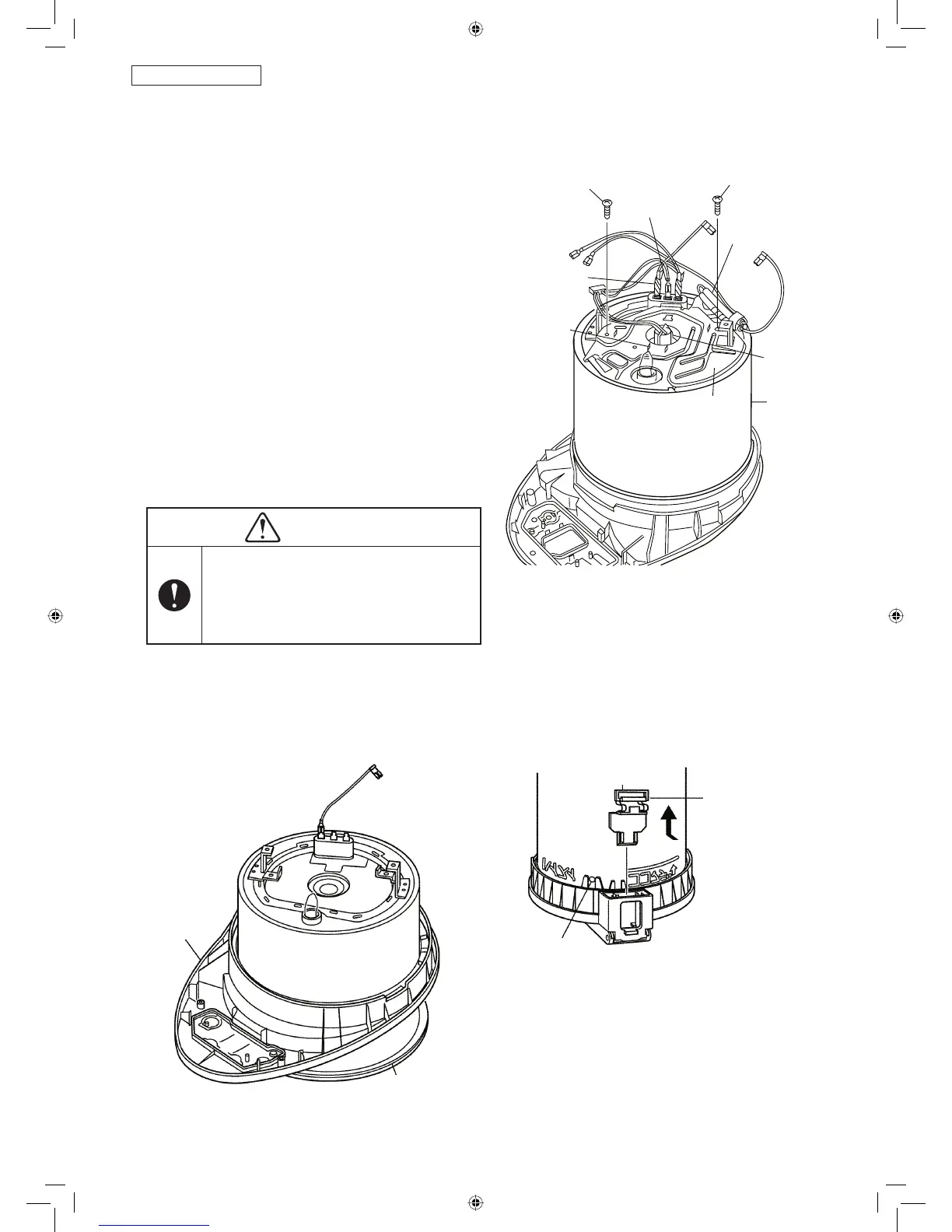
DISASSEMBLY-7
w Remove this
portion in the
manner indicated
with the arrow.
DISASSEMBLY-8
- 15 -
NC-BH30P, BH40P
1. Remove the screws from the thermal insulator cover.
2. Remove the orange, white and yellow wires from the
heater terminals.
3. Remove the thermal insulator cover from the body.
4. Remove the nonfl ammable tube B.
5. Remove the thermal fuse comp. from the thermal
insulator cover.
6. Remove the holding spring A of the thermistor comp.
from the thermal insulator cover.
7. Before removing the thermistor comp. from holding
spring A, turn it 90 degrees.
Service point
• Remove the orange, white, and red lead wires with
long nose type pliers.
Point in reassembly
• Do not mishandle the thermal fuse comp. such as
pulling, bending or twisting.
• In assembling thermistor comp., be careful of
gradient.
• In assembling thermistor comp., make sure to apply
the lubricating agent A.
CAUTION
If the lubricating agent A is not applied
during the thermistor assembly, sensitiv-
ity of thermistor becomes worse.
When assembling the thermistor, make sure
to apply the lubricant agent A provided.
3.7. Thermal Fuse comp. and Thermistor comp.
3.8. Pouring spout and lock lever A (knob for opening and closing the cover)
4x8 Deltite screws
1. Remove the cover comp.
2. Remove the pouring spout.
3. Remove the lock lever A toward upper side by
pushing it while pushing down.
4. Remove the container packing.
Point in Reassembling
• When reassembling the pouring spout, insert the
dowel of container comp. into the 2 long ribs. (refer to
“Knob” in below diagram)
4x8 Deltite screws
Heater terminal
Nonfl ammable
tube B
Clamps to hold
spring A
Thermal fuse
comp.
Thermistor
comp.
Thermal insulator
cover
Body comp.
Lock lever A
Knob
Pouring
spout
Container packing
• The container packing shall closely contact the
container fl ange without twisting or distortion.
NC-BH40-30-22.indd 15NC-BH40-30-22.indd 15 14-08-07 16:48:0314-08-07 16:48:03
 Loading...