EasyManua.ls Logo

Panasonic RQ-320SD User Manual

Panasonic RQ-320SD
44 pages
To Next Page IconTo Next Page
Page #1 background imageLoading...
Page #1 background image
ORDER
NO.
ARD-7507062S
Service
Manual
Portable
Cassette
Recorder
RQ-320SD
Deluxe
Portable
AC/Battery
Cassette
Recorder
with
Detachable/Built-in
Condensor
Microphone
a
RQ-237S
MECHANISM
SERIES
Specifications
(Catalog
specifications
for
sales)
Power
requirement:
Motor
:
Frequency
response:
Recording
system:
Operation:
Tape
speed:
National
Panasonic
AC;
220V,
50Hz
Power
consumptions;
6W
Battery;
6V
(four-R14
size
dry
batteries)
Car/boat
battery;
with
optional
car/boat
adaptor
RP-914-E
Rechargeable
battery;
with
optional
rechargeable
battery
pack
RP-092
DC
mechanical
motor
50~11,000
Hz
(with
CrOz
tape)
50~10,000
Hz
(with
REGULAR
tape)
AC
bias,
AC
erase
Pushbutton
operation
with
Auto-Stop
mechanism
4.8cm/s
I
oo:
oe
Program
time:
Fast
forward
and
rewind
time:
Track
system:
Input:
Output:
REC/PB
connection:
Speaker:
Dimensions:
Weight:
1
hour
with
C-60
cassette
tape
Approx.
90
seconds
with
C-60
cassette
tape
2-track
monaural
recording
and
playback
MIC;
sensitivity
0.28
mV/applicable
microphone
impedance
2002~6002
AUX;
sensitivity
100
mV/180
K2
DC
IN;
6V
EXT
SP;
8Q
REMOTE;
for
start
and
stop
at
hand
5P
DIN
type
10cm
PM
dynamic
speaker
23.5em(W)
X27.2cm(H)
X8.5cm(D)
3kg
Specifications
are
subject
to
change
without
notice
for
further
improvement.
Matsushita
Electric
Trading
Co.,
Ltd.
P.O.
Box
288,
Central
Osaka
Japan
Question and Answer IconNeed help?

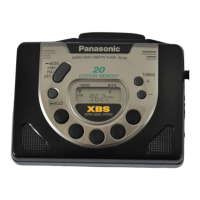
Do you have a question about the Panasonic RQ-320SD and is the answer not in the manual?

Panasonic RQ-320SD Specifications

General IconGeneral
BrandPanasonic
ModelRQ-320SD
CategoryCassette Player
LanguageEnglish

Summary

Specifications

Technical Diagrams

Schematic Diagram

Detailed circuit diagram of the portable cassette recorder.

Wiring Diagrams

Diagrams showing electrical wiring and color coding for connections.

Parts Identification

Location of Parts

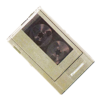
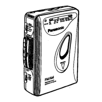
Illustrations and labels identifying all external and internal parts.

Maintenance Procedures

Disassembly Instructions

Steps for safely disassembling the device, starting with the bottom case.

Chassis Removal

Detailed instructions for removing the main chassis from the unit.

Adjustments

Mechanical Adjustments

Procedures for adjusting mechanical components like pressure rollers and tape tension.

Amplifier Adjustments

Procedures for adjusting amplifier circuits, including head angle and bias.

Alignment Procedures

FM IF & Detector Alignment

Detailed steps for aligning FM IF and detector circuits using an oscilloscope.

FM RF Alignment

Instructions for aligning FM RF circuits, including antenna and oscillator adjustments.

Parts Lists & Locations

Replacement Parts List

Comprehensive list of all replacement parts with their reference numbers and part numbers.

Electrical Parts Location

Diagrams showing the physical location of electrical components on the circuit board.

Circuit Board & Views

Exploded Views

Illustrations showing how the device components are assembled together.

Circuit Board Diagram

Detailed schematic of the main circuit board with component layout and voltage points.

Cabinet & Packing Details

Cabinet Parts

List and diagrams of the external casing and cosmetic parts of the device.

Component Packing

Diagrams illustrating the packing method for components and the final product.

Related product manuals