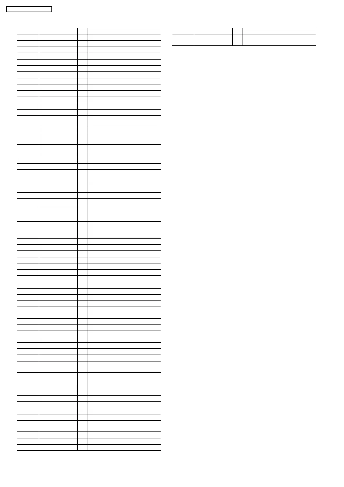
Pin No. Mark I/O Function
45 NC - No connection
46 PCONT/EFP_/CE O Main transformer control output
47 DCDET I DC detect input
48 SP_A O Speana control output A
49 SP_B O Speana control output B
50 SP_C O Speana control output C
51 NC - No connection
52 HALF_1 I Deck 1 half playback input
53 MODE_1 I Deck 1 mode playback input
54 PHOTO_2 I Rotation detection signal (Deck 2)
55 PHOTO_1 I Rotation detection signal (Deck 1)
56 PLG1 O Deck 1 plunger control
57 PLG2 O Deck 2 plunger control
58 MTR O Deck motor control
(“H” for motor ON)
59 REC O H when record circuit is operating
60 DECK1_H O H when DECK 1 P/B head is
selected
61 NC - No connection
62 Vcc - Power supply (+5V)
63 NC - No connection
64 Vss - Ground (0V)
65 DMT O Deck mute at mecha transition
(“L” for MUTE ON)
66 BP1 O AM beatproof 1 output
(“H” for BP1 ON)
67 V_JOG_A I Volume Jog A
68 V_JOG_B I Volume Jog B
69 EX1_CLK O I/O expander clock output (for
AK620)
(Subwoofer and Jog LED control)
70 EX1_DAT O I/O expander data output (for
AK520)
(Subwoofer and jog LED control)
71 FL_RESET I Reset input (ACTIVE L)
72 FL_CS I/O FL driver chip select
73 FL_DOUT O Serial data to FL driver (Output)
74 FL_CLK I/O Serial clock to FL driver
75 /CD O CD power control (Active low)
76 SSEQ_LED O Super Sound EQ LED
77 CD_RST O CD reset output
78 STATUS I CD Servo LSI status input
79 MLD O CD command load output
80 MDATA O CD command data output
81 MCLK O CD command clock output
82 /RESTSW I CD limit switch input for the most
inner point (Active Low)
83 CHG_HLF O Changer half drive output
84 CHG_CW O Changer motor clockwise output
85 CHG_CCW O Changer motor counterclockwise
output
86 CHG_SW1 I CD changer switch 1 input
87 CHG_SW2 I CD changer switch 2 input
88 CHG_PLR O Changer plunger output
89 CHG_AD2 I Changer AD detecton input
(Position/Bottom)
90 CHG_AD1 I Changer AD detecton input
(Open/Clamp)
91 DECK2 I DECK CONDITION INPUT 2
(R_INHF/MODE2/R_INHR/HALF2)
92 KEY3 I KEY3 INPUT
93 KEY2 I KEY2 INPUT
94 KEY1 I KEY1 INPUT
95 REG_2 I Region setting 2
96 AVss - Analog power supply input
(Connect to GND)
97 REG1 I Region setting 1
98 VREF - Reference for A-D (5V)
99 AVcc - Analog power supply input
Pin No. Mark I/O Function
100 DEMO
SELECTOR
I (H= default demo on, L= default
demo off.)
82
SA-AK220E / SA-AK220EB
 Loading...