Do you have a question about the Panasonic SA-AK87 and is the answer not in the manual?
| Brand | Panasonic |
|---|---|
| Model | SA-AK87 |
| Category | Stereo System |
| Language | English |
Safety warnings regarding electrical shock and prior steps before repair.
Information on protecting the unit from damage and troubleshooting steps.
Guidelines for handling the traverse deck to prevent static discharge damage.
Procedures for grounding to prevent damage from static electricity.
Warnings and guidelines regarding the safe handling and operation of the laser diode.
Explains the meaning and importance of caution labels on the product.
Instructions for connecting the FM indoor antenna for optimal reception.
Instructions for connecting the AM loop antenna for best reception.
Details on connecting front, surround, center speakers, and video output.
Instructions for connecting FM indoor, AM loop antennas, and various speakers.
Steps to connect the video cable and AC power cord.
Instructions on how to set the voltage selector for different regions.
How to connect DVD and Laser Disc players for playback.
Steps to connect a video cassette recorder for recording or playback.
Instructions for connecting a record player for audio input.
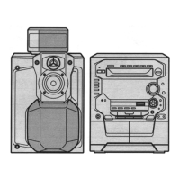
Detailed description of buttons and indicators on the main system unit.
Explanation of controls and indicators found on the center console unit.
Procedure to set the correct time on the unit's display.
How to view the clock display when the unit is on or off.
Steps for performing a sequential recording of a CD onto tape.
Explanation of buttons and functions used during CD recording.
How to choose the recording mode (1-TRACK, ALL, etc.) for CD recording.
Procedure for selecting and recording individual tracks from a CD.
Steps for setting up and recording radio programs.
Techniques to minimize noise when recording AM radio broadcasts.
Step-by-step process for dubbing tapes between decks.
Details on servicing gears and performing basic maintenance.
Steps to inspect and verify the functionality of the main circuit board.
Guide for checking the panel circuit board for proper operation.
Procedures for verifying the Digital Signal Processor and deck circuit boards.
Steps to inspect and test the power circuit board.
Instructions for safely removing and installing the traverse deck unit.
Steps for installing the traverse deck onto the CD servo circuit board.
Guide for replacing the power amplifier IC.
Guide for replacing regulator transistors.
Procedures for safely disassembling the traverse unit.
Steps to reassemble the traverse unit correctly.
Procedures for taking apart the disc tray.
Steps to reassemble the disc tray.
Steps for correctly installing gears and the disc tray.
Steps to activate the unit's self-diagnostic testing feature.
Lists and explains error codes related to the cassette mechanism.
Details specific error codes for CD playback and repeat functions.
Procedure to reset and clear recorded error codes from the system.
Detailed error codes and their associated problem conditions for the cassette deck.
Error codes specific to the CD playback and changer mechanisms.
Error codes indicating issues with the power supply unit.
Explanation of the automatic alignment function and its error codes.
Detailed explanation of error codes related to CD alignment results.
Detailed steps for adjusting azimuth on the cassette decks.
Detailed steps for adjusting tape speed on the cassette decks.
Procedures for checking bias and erase voltages in the cassette deck.
Instructions for aligning the FM and AM tuner sections.
Detailed steps for aligning the AM and FM tuner sections of the system.
Lists specific points for alignment within the cassette deck section.
Illustrations of expected signal waveforms for troubleshooting Video CD functions.
Symptom-based troubleshooting steps for Video CD issues.
Interpretation of master and audio data clock waveforms for troubleshooting.
Troubleshooting steps based on observed symptoms for CD-DA and Video CD.
Step-by-step guide for troubleshooting CD-DA playback problems, focusing on sound output.
Steps to troubleshoot Video CD playback problems, including picture and sound.
Steps to diagnose problems related to the blue back screen on Video CDs.
Pin functions for the IC701 servo amplifier IC.
Pin functions for the IC703 motor drive IC.
Pin functions for the IC702 digital sound processor IC.
Pin functions for the IC381 system microcontroller IC.
Pin functions for the IC201 digital sound controller IC.
Pin functions for the IC451 system control IC.
Pin functions for the IC1000 MPEG video/audio decoder IC.
Pin functions for IC1001, IC1002, IC1003, and IC1004.
Explanation of symbols used to represent different signal lines in the schematics.
Critical safety information regarding component handling and precautions.
Identifies key components within the servo circuit diagram.
Details the signal routing for IC702 and IC703 within the schematic.
Identification of components within the video circuit schematic.
Diagram showing connections and functions of memory and decoder ICs.
Identification of components within the DSP circuit schematic.
Diagrams showing connections for audio and system control integrated circuits.
Diagrams for power transformer, sub-transformer, and motor control circuits.
Schematics for CD detection and spindle position sensing circuits.
Identifies key components within the deck circuit diagram.
Details on how ICs and transistors are interconnected in the circuit.
Schematic detailing the operation of the Deck 1 mechanism.
Schematic detailing the operation of the Deck 2 mechanism.
Identifies components within the main and tuner circuit diagram.
Diagrams showing connections for audio and control ICs.
Diagrams detailing digital processing ICs and their interconnections.
Diagrams showing ICs and transistors for electronic volume control.
Diagrams showing ICs involved in signal amplification and system control.
Diagrams showing connections and functions of the microcontroller IC.
Schematic for the CD tact switch circuit.
Identifies components within the panel circuit diagram.
Diagrams showing connections for the front panel FL display.
Diagrams showing ICs and transistors used in control and indicator functions.
Identifies components within the power circuit diagram.
Layout of the Servo P.C.B. with component locations.
Layout of the Main/Tuner P.C.B. with component locations.
Tables cross-referencing component references with their locations on PCBs.
Layout of the Panel P.C.B. with component locations.
Additional tables cross-referencing component references with their locations on PCBs.
Layouts of the tact switch P.C.Bs with component locations.
Layouts of the mechanism P.C.Bs for Deck 1 and Deck 2.
Layouts of the motor and CD detect P.C.Bs.
Layout of the Deck P.C.B. with component locations.
Tables cross-referencing component references with their locations on PCBs.
Layout of the Power P.C.B. with component locations.
Layout of the transformer P.C.B. with component locations.
Layouts of the sub-transformer and voltage selector P.C.Bs.
Layout of the DSP P.C.B. with component locations.
Layout of the Video P.C.B. with component locations.
Block diagram of the servo amplifier, showing signal flow and components.
Block diagram of the motor drive system, detailing control signals.
Diagram illustrating the digital signal processing and D/A conversion stages.
Illustrates functional blocks of memory and video/audio decoder ICs.
Block diagram showing the tuner's signal path and processing.
Block diagram of the frequency synthesizer for tuning control.
Diagram showing the functional blocks of the motor drive controller.
Block diagram of the system controller managing overall operations.
Diagram for the playback equalizer and TPS amplifier.
Diagram for the recording amplifier and repeat playback functions.
Diagram of the digital sound processor and its functions.
Block diagram for the karaoke expansion unit.
Diagrams illustrating analog selector functions.
Block diagram of the microcontroller and its control pathways.
Diagram of the power amplifier stage.
Diagrams illustrating system control functions.
Diagram of the spectrum analyzer module.
Block diagram of the system control unit.
Illustration of signal flow within the power amplifier.
Illustration of how different printed circuit boards connect to each other.
Step-by-step guide for troubleshooting CD playback problems.
Detailed exploded view of parts for the Deck 1 mechanism.
Detailed exploded view of parts for the Deck 2 mechanism.
Details on playback, fast forward, and rewind torque specifications.
Detailed list of all parts for the cassette deck mechanism.
Detailed list of parts for the CD loading mechanism.
Identification of specific components within the CD loading unit.
Details on assembling the CD loading unit.
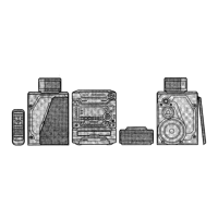
Identification of various parts that make up the system's cabinet.
Identification of where internal printed circuit boards are mounted.
List of replacement parts for the cabinet and chassis.
List of replacement integrated circuits.
List of replacement transistors.
List of replacement diodes.
List of replacement variable resistors.
List of replacement switches.
Detailed list of replacement transistors.
Detailed list of replacement diodes.
Detailed list of replacement variable resistors.
Detailed list of replacement switches.
Detailed list of replacement connectors.
List of replacement coils and transformers.
List of replacement oscillators and ceramic filters.
List of replacement display tubes and fuses.
List of replacement jacks, earth terminals, and wires.
List of resistors with their part numbers and values.
Detailed listing of resistor values and power ratings.
Comprehensive details on resistor part numbers, values, and remarks.
Specifications for resistors, including part numbers and values.
List of capacitors with their part numbers, values, and voltage ratings.
Detailed specifications for capacitors, including part numbers and voltage ratings.
Comprehensive details on capacitor part numbers, values, and voltage ratings.
Lists for capacitors, chip jumpers, and test jumpers.
List of materials used for packing the system.
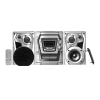
List of included accessories such as remote controls and cables.