Do you have a question about the Panasonic SA-HT280 and is the answer not in the manual?
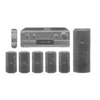
Overview of technical details for the AV Control Stereo Receiver.
Procedure to ensure electrical safety after repair by measuring resistance.
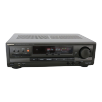
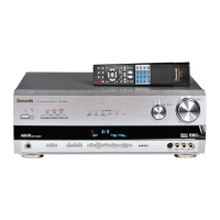
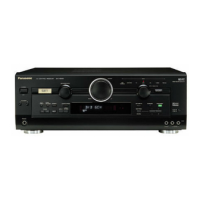
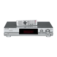
Detailed layout and function of the primary controls on the main receiver unit.
Explanation of indicators and information displayed on the unit's front panel.
Identification of buttons and their respective functions on the remote control.
Steps for inspecting Front Panel, Surround, and IN/OUT terminal PCBs.
Procedure for inspecting the DTS Printed Circuit Board.
Procedure for inspecting the main Printed Circuit Board.
Steps for replacing power IC and regulator transistors.
Explanations and conventions used in the schematic diagrams for clarity.
Pinout and function details for the M38B57M6141F microprocessor.
Detailed schematic of audio and digital input/output connections.
Schematic detailing the surround sound signal paths and processing components.
Schematic detailing the digital surround sound (DTS) signal path.
Schematic illustrating the front panel display driver circuitry and controls.
Schematic showing connections and components for the headphone output.
Schematic of the primary audio signal paths and amplification stages.
Schematic of the unit's power supply section.
Schematic detailing the power transformer and its connections.
Schematic for AC input and output connections.
Schematic of the tuner section, including PLL frequency synthesizer.
| Type | Stereo Receiver |
|---|---|
| Channels | 5.1 |
| Frequency Response | 20Hz - 20kHz |
| Speaker Impedance | 6 ohms |
| Power Output | 100W per channel (6 ohms, 1kHz, 10% THD) |