65
(IC2903).
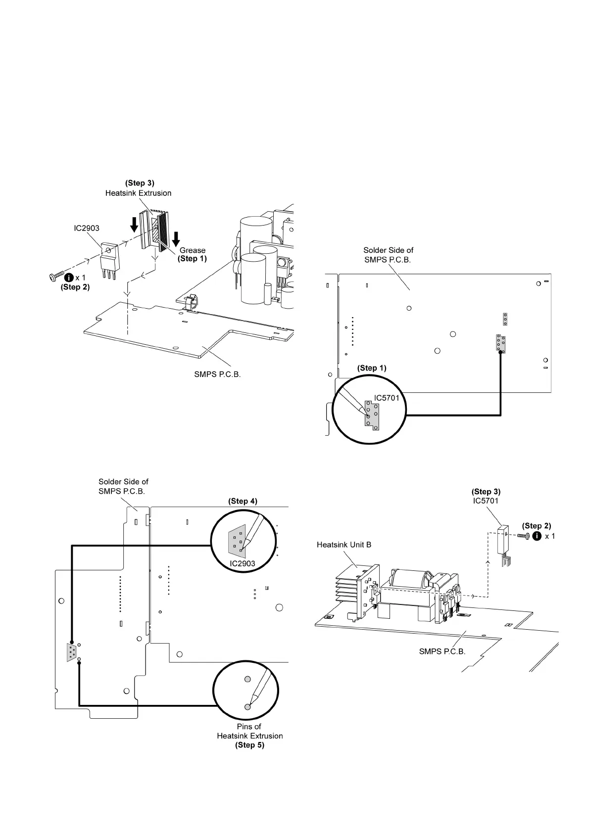
Step 5 Remove the switching regulator IC (IC2903) from the
heatsink extrusion.
Caution: Handle the heatsink extrusion with caution due to
its high temperature after prolonged use. Touching it may
lead to injuries.
Note: Refer to the diagrams of SMPS P.C.B. (Item 18.5.) for
location of the electrical components.
9.20.2. Assembly of Switching Regulator
IC (IC2903)
Step 1 Apply grease to the heatsink extrusion.
Step 2 Fix and screw the switching regulator IC (IC2903) to the
heatsink extrusion.
Step 3 Mount the heatsink extrusion with switching regulator
(IC2903) on the SMPS P.C.B.
Note: Ensure the switch regulator IC (IC2903) is tightly
screwed to the heatsink extrusion.
Step 4 Solder pins of the switching regulator IC (IC2903) on the
solder side of SMPS P.C.B.
Step 5 Solder pins of the heatsink extrusion on the solder side
of SMPS P.C.B.
Caution: Ensure pins of the switching regulator IC (IC2903)
are properly seated and soldered on SMPS P.C.B.
9.21. Replacement of Switching Reg-
ulator IC (IC5701)
9.21.1. Disassembly of Switching Regula-
tor IC (IC5701)
• Follow (Step 1) to (Step 3) of Item 9.3.
• Follow (Step 1) to (Step 10) of Item 9.6.
• Follow (Step 11) to (Step 13) of Item 9.12.
• Follow (Step 1) to (Step 7) of Item 9.19.
Step 1 Desolder pins of the switch regulator IC (IC5701) on the
solder side of SMPS P.C.B.
Step 2 Remove 1 screw from the switching regulator IC
(IC5701).
Step 3 Remove the switching regulator IC (IC5701) from the
heatsink unit B.
Caution: Handle the heatsink unit B with caution due to its
high temperature after prolonged use. Touching it may
lead to injuries.
Note: Refer to the diagrams of SMPS P.C.B. (Item 18.5.) for
 Loading...