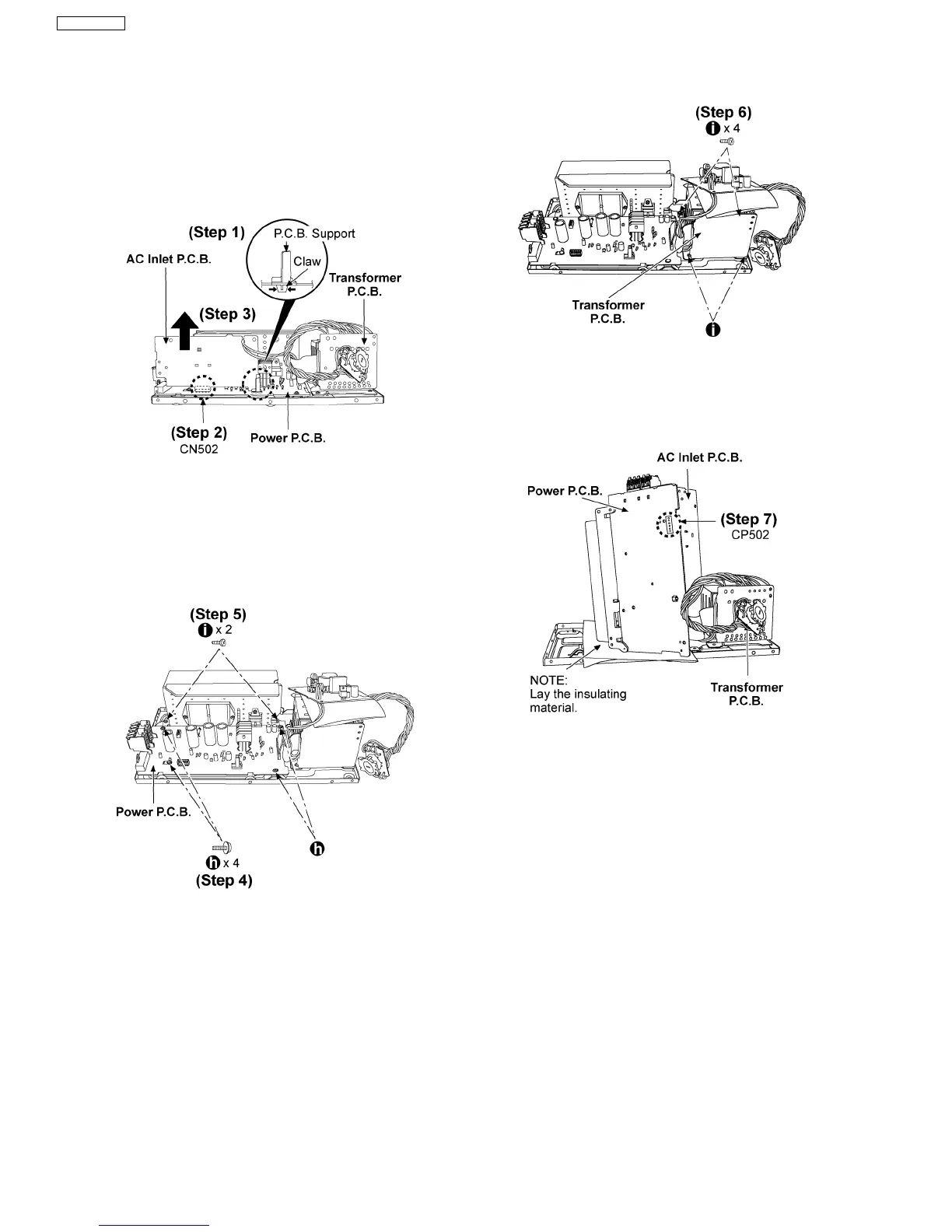
7.2.6. Disassembly and checking of the
AC Inlet P.C.B., Power P.C.B. and
Transformer P.C.B.
Follow Step (1) to Step (5) described in section 7.2.4.
Follow Step (1) to Step (4) described in section 7.2.5.
Step 1: Remove the P.C.B. support by pushing the claws as
arrow shown.
Step 2: Disconnect the connector (CN502).
Step 3: Lift up the AC Inlet P.C.B. as arrow shown.
Step 4 & 5: Remove 8 screws.
Step 6: Remove 4 screws.
Step 7: Connect back the connector CP502 between Power
and AC Inlet P.C.B. for checking.
7.2.7. Replacement of Power IC and
Transistor
Follow Step (1) to Step (5) described in section 7.2.4.
Follow Step (1) to Step (4) described in section 7.2.5.
12
SB-WA730GCP
 Loading...