Do you have a question about the Panasonic SC-CMAX5GS and is the answer not in the manual?
| Brand | Panasonic |
|---|---|
| Model | SC-CMAX5GS |
| Category | Speaker System |
| Language | English |
General safety guidelines for servicing the unit, emphasizing important notices.
Safety precautions related to the AC cord, specifically for GS models.
Instructions to be followed before operating the unit for PH models.
Important precautions to take before performing any repair or adjustment on the unit.
Explanation of the unit's protection circuitry and its operational conditions.
Information and list of critical safety components that require specific replacement.
Techniques to prevent damage to sensitive electronic components from electrostatic discharge.
Cautions and guidelines for servicing based on legal restrictions, like lead-free solder use.
Overview of the service manual's technical information and guidance on ordering parts.
General information including power consumption, power supply, dimensions, mass, and operating conditions.
Details on the amplifier section, including output power ratings for different channels.
Specifications for the terminal section, covering USB ports, jacks, and audio connections.
Specifications for the Bluetooth section, including version, class, profiles, and operation distance.
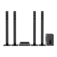
Specifications for the speaker section, listing driver types for front, mid, and subwoofer.
Details the key button operations for the main unit and remote control for PH/PR models.
Details the key button operations for the main unit and remote control for GS models.
Procedure to enter and use the self-diagnostic mode for checking unit status and errors.
Information on error codes displayed during self-diagnosis for power supply and Bluetooth issues.
Procedures and tables for operating the Doctor Mode for detailed system checks and data display.
Steps to reset the unit to factory shipment status, including power button sequence.
Instructions on how to enter the Doctor Mode for accessing various diagnostic functions.
Disassembly flow chart, type of screws used, and main parts location diagram for guidance.
Step-by-step guides for disassembling individual components such as panels, speakers, and PCBs.
Procedures for checking the SMPS Module, Voltage Selector PCB, and Main PCB assembly.
Procedures for checking the Bluetooth, Panel, and FL Display PCBs after assembly.
Block diagrams illustrating the system control functions across three parts.
Block diagrams detailing the audio signal processing and pathways in three parts.
Block diagrams showing the power supply circuits and voltage regulation in two parts.
Diagram illustrating the wiring connections between major components and PCBs.
Notes on schematic diagram modifications, safety notices, and definitions of symbols and signal lines.
Schematics for Main SOC, USB, DSP, DAMP, VREG FAN, and Connector circuits.
Schematics for Panel circuits (3 parts) and the FL Display circuit.
Layout diagrams for the Main PCB Assembly, showing component placement on both sides.
Layout diagrams for the Panel PCB and the FL Display PCB, indicating component positions.
Tables providing standard voltage values for various ICs and components on the Main, Panel, and FL Display PCBs.
Exploded views illustrating the location of cabinet parts for replacement or identification.
Diagram showing the contents of the product packaging, including accessories and protective materials.
Lists of mechanical and electrical replacement parts with part numbers, descriptions, and quantities.