32
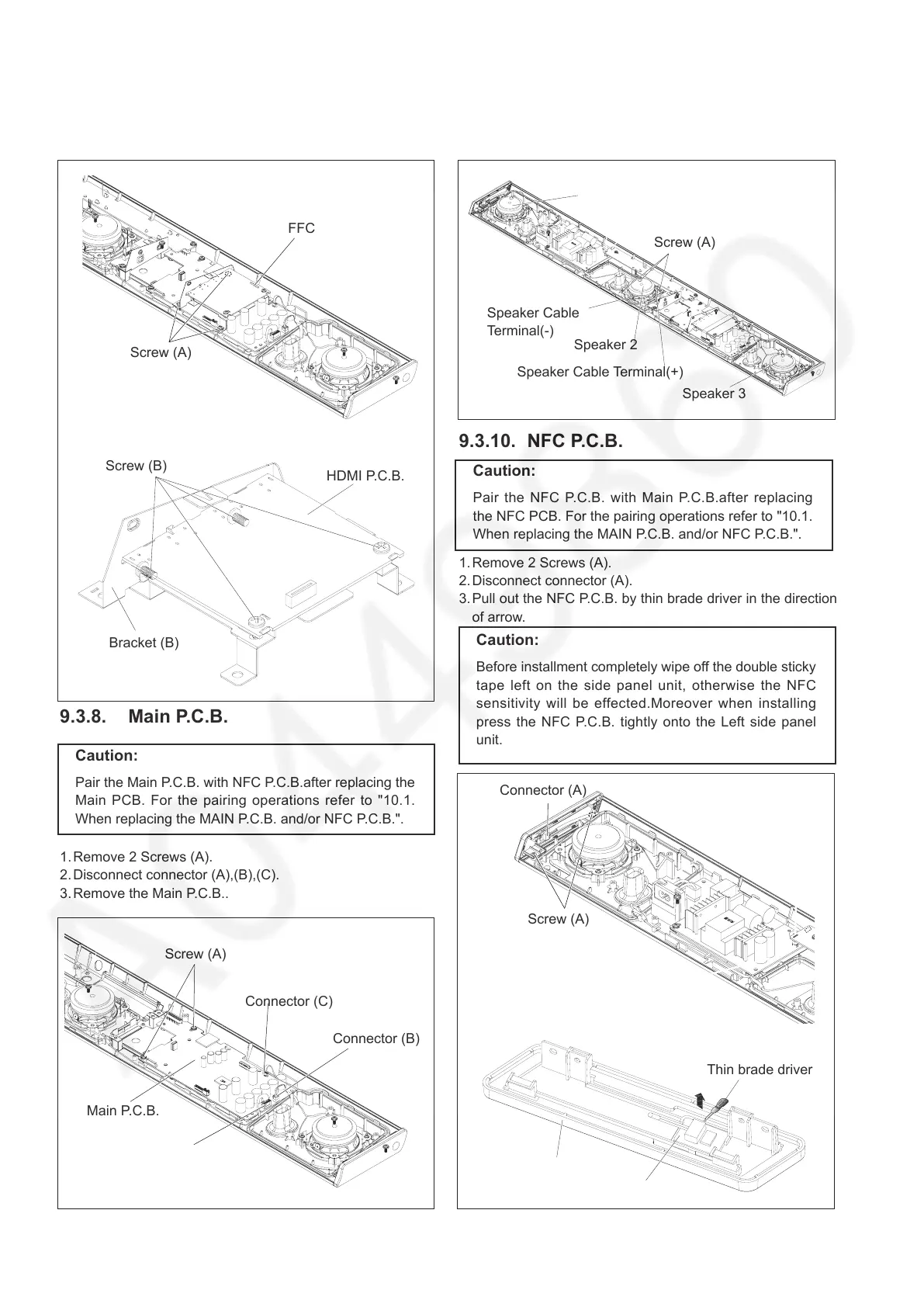
9.3.10. NFC P.C.B.
1. Remove 2 Screws (A).
2. Disconnect connector (A).
3. Pull out the NFC P.C.B. by thin brade driver in the direction
of arrow.
Screw (A)
9.3.7. HDMI P.C.B.
1. Remove 3 Screws (A).
2. Disconnect FFC cable.
3. Remove 4 Screws (B).
4. Remove Bracket (B) and HDMI P.C.B..
Screw (A)
Screw (B)
9.3.8. Main P.C.B.
1. Remove 2 Screws (A).
2. Disconnect connector (A),(B),(C).
3. Remove the Main P.C.B..
Main P.C.B.
Connector (A)
9.3.9. Speaker
1. Disconnect 2 Speaker Cable Terminals.
2. Remove 3 Screws (A).
3. Remove the Speaker 2.
(Remove Speaker 1,3 by the same method.)
Screw (A)
Screw (A)
HDMI P.C.B.
FFC
Bracket (B)
Connector (B)
Connector (C)
Speaker Cable
Terminal(-)
Speaker 2
Speaker 1
Speaker 3
Speaker Cable Terminal(+)
Connector (A)
Thin brade driver
NFC P.C.B.
Left side panel unit
Caution:
Pair the Main P.C.B. with NFC P.C.B.after replacing the
Main PCB. For the pairing operations refer to "10.1.
When replacing the MAIN P.C.B. and/or NFC P.C.B.".
Caution:
Before installment completely wipe off the double sticky
tape left on the side panel unit, otherwise the NFC
sensitivity will be effected.Moreover when installing
press the NFC P.C.B. tightly onto the Left side panel
unit.
Caution:
Pair the NFC P.C.B. with Main P.C.B.after replacing
the NFC PCB. For the pairing operations refer to "10.1.
When replacing the MAIN P.C.B. and/or NFC P.C.B.".
 Loading...