EasyManua.ls Logo

Panasonic SG-40 User Manual

Panasonic SG-40
24 pages
To Next Page IconTo Next Page
Page #1 background imageLoading...
Page #1 background image
ORDER
NO.
TSD81070013¢C
Service
Manual
FM/AM/FM
STEREO
WITH
CASSETTE
TAPE
DECK
DO
eaarssrew)
eet
iilll
*’'Dolby”
and
the
double-D
symbol
are
trademarks
of
Dotby
Laboratories
Licensing
Corporation.
“Noise
Reduction
System
manufactured
under
license
from
Dolby
Laboratories
Licensing
Corporation.
SPECIFICATIONS
AMPLIFIER
SECTION
Power
Output:
MPO
.............
35Wx
2
(THD
1%,
42)
BMSi
suze
Pages
acer
a
tea aed
4
27W
x
2
(THD
1%,
42)
25W
x
2
(THD
0.8%,
42)
One
channel
driven
RMS
.............
22Wx
2(THD
1%,
4Q)
20W
x
2
(THD
0.8%,
42)
Both
channel
driven
Frequency
Response...
..
30Hz~40
kHz,
+1.5
dB
(DIN)
Power
Band
Width
......
25
Hz
~
25
kHz,
-3
dB
(DIN)
(THD
0.9%,
42)
Input
Sensitivity
&
Impedance:
WIG
boc
alo
eS
1
mV,
3k2
PIR
eS
eae
eee
150
mV,
47kQ
PHONO!
2.5
oe
ae
a
ee
2.5
mV,
47kQ2
Rec
Out
&
Impedance...
.
150
mV,
2.2k2
Tone
Controls:
BaS$i5
i050
354
a
nbd
+10
dB
at
50
Hz
Treble.
2...
2.
.00..
+10
dB
at
15
kHz
Loudness
Control
......
+10
dB
at
50
Hz
(Volume
at
-30
dB
position)
FM
TUNER
SECTION
TuningSystem
........
Varactor
Diode
(6
pre-selectors
and
1
manual
tuning)
Frequency
Range.
......
87.5
MHz
~
108
MHz
Intermediate
Frequency
(IF)
.
10.7
MHz
Sensitivity...
...0000.
2.0uV
(S/N
26
dB
mod.
40
kHz)
(DIN)
at
762
2.0nV
(IHF)
at
752
Image
Ratio.
.....002..
50
dB
(98
MHz)
Signal/Noise
Ratio
......
63
dB
(at
1
kHz,
60
dB,
40
kHz)
Distortion:
MONO............
0.16%
(at
1
kHz,
60
dB,
40
kHz)
STEREO
..........
0.22%
(at
1
kHz,
60
dB,
40
kHz)
Stereo
Separation
......
40
dB
(at
1
kHz,
60
dB,
40
kHz)
35
dB
(at
250
Hz
~
6.3
kHz,
60
dB,
AO
kHz)
(DIN)
33
dB
(at
6.3
kHz
~
10
kHz,
60
dB,
40
kHz)
(DIN)
Selectivity.
2
0.0...
000.
70
dB
(at
1
kHz,
60
dB,
40
kHz)
Panasonic
Stereo
Music
Centre
SG-40
“Hi
Covet
des
Reese
Panssonic
AM
TUNER
SECTION
Frequency
Range...
....
MW;
525
kHz
~
1605
kHz
(571m
~
187m)
LW;
150
kHz
~350
kHz
(2000m
~
875m)
Intermediate
Frequency
(IF)
.
455
kHz
Sensitivity.
..........
MW;
110uV/m
(1
MHz)
LW;
250uV/m
(240
kHz)
Image
Ratio...
2...
0...
MW;
50
dB
(1
MHz)
LW;
35
dB
(240
kHz)
TAPE
DECK
SECTIO
Deck
System
.........
Full
Auto
Shut
Off
Cassette
System
Track
System
.........
4-Track,
2-Channel
Recording
System
......
AC
Bias
(50
kHz)
with
Dolby
NR
System
ErasingSystem
........
AC
Erase
(50
kHz)
TapeSpeed
..........
4.75
cm/sec.
(1-7/8
i.p.s.)
Frequency
Response.
....
20
Hz
~
15
kHz
(Normal)
20
Hz
~
16
kHz
(CrO2)
20
Hz
~
17
kHz
(Metal)
Signal/Noise
Ratio:
DOLBY
NR-OUT
.....
53
dB
(Normal)
55
dB
(CrO2)
ron
55
dB
(Metal)
DOLBY
NR-IN.....
..
61
dB
(Normal))
(10
dB
or
more
63
dB
(CrO2)
}improved
at
63
dB
(Metal)
/5
kHz)
(DIN)
Erase Ratio
..........
70
dB
(DIN)
Channel
Separation
.....
40
dB
(DIN)
CrossTalk...
........
60
dB
(DIN)
Wow
&
Flutter
2...
2.0...
0.05%
(WRMS),
0.15%
(DIN-WTD)
POWER
CONSUMPTION
..
160
W
POWER
SUPPLY.......
AC
220
V,
50/60
Hz
DIMENSIONS
(WxHxD)
.
430x
124
x
318
mm
WEIGHT
...........
7.2
kg
*
Specifications
are
subject
to
change
without
notice
for
further
improvement.
Matsushita
Electric
Trading
Co.,
Ltd.
P.
O.
Box
288,
Central
Osaka,
Japan
Question and Answer IconNeed help?

Do you have a question about the Panasonic SG-40 and is the answer not in the manual?

Panasonic SG-40 Specifications

General IconGeneral
TypeStereo System
Power Output12 W per channel (min RMS)
Dimensions450 x 150 x 370 mm
Weight9 kg
Input Sensitivity150mV

Summary

Specifications

Amplifier Section

Details electrical specifications for the amplifier section.

FM Tuner Section

Lists technical specifications for the FM tuner.

AM Tuner Section

Details the specifications for the AM tuner.

Tape Deck Section

Provides technical specifications for the cassette tape deck.

Location of Controls

Control Panel Overview

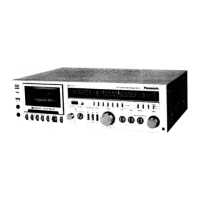
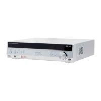
Identifies and labels the various controls on the front panel.

Disassembly Instructions

Component Removal Steps

Step-by-step guide for disassembling the unit and its components.

Cassette Tape Deck Alignment

Bias Alignment Procedures

Steps for aligning the tape deck's bias settings.

Azimuth, Dolby, and Rec Current Alignment

Procedures for aligning azimuth, Dolby, and recording current.

Alignment Test Points

Identifies specific test points for cassette tape deck alignment.

Dial Cord Stringing Guide

Dial Cord Routing

Instructions and diagram for routing the dial cord.

Radio Alignment Points

Radio Alignment Test Points

Identifies test points for radio alignment procedures.

Radio Alignment Procedures

AM-IF and RF Alignment

Steps for aligning AM Intermediate Frequency and Radio Frequency stages.

FM Alignment Procedures

Instructions for various FM alignment tasks including IF, RF, Stereo, Muting.

VU Meter Alignment

Steps for calibrating the VU meters.

Schematic Diagram

Circuit Diagram Overview

Visual representation of the electronic circuitry of the SG-40.

Circuit Board and Wiring Connections

PCB Layout and Wiring

Diagrams showing the layout of circuit boards and their wiring connections.

Wiring Connection Details

Specific Connection Points

Diagrams illustrating wiring connections at various points like P2, P3, P8, P9.

Replacement Parts List

Resistor Specifications

List of resistors with part numbers, descriptions, and specifications.

Capacitor Specifications

List of capacitors with part numbers, descriptions, and specifications.

Cabinet and Chassis Parts

List of replacement parts for the cabinet and chassis.

Cassette Tape Deck Parts

List of replacement parts specific to the cassette tape deck.

Parts Location - Cabinet and Chassis

Component Placement Diagrams

Diagrams showing the physical location of cabinet and chassis parts.

Exploded View - Cassette Tape Deck

Cassette Deck Component Assembly

Exploded view diagram showing the assembly of cassette tape deck components.

Block Diagram

System Functional Blocks

Diagram illustrating the functional blocks and signal flow of the SG-40.
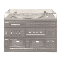
Related product manuals